Sharp XV-Z21000 (serv.man7) Service Manual ▷ View online
XV-Z20000/XV-Z21000/DT-5000
2 – 6
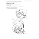
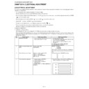
[6] Removing the Optical mechanism unit, R/C Front PWB and IRIS Drive PWB
1. Remove the four connectors.
2. Remove the six screws and detach the Optical mechanism unit.
3. Remove the one screw and the one connector. Detach the R/C Front PWB.
4. Remove the two hooks and detach the IRIS Drive PWB.
6-2
6-1
6-1
Optical mechanism unit
6-3
6-4
R/C Front PWB
IRIS Drive PWB
XV-Z20000/XV-Z21000/DT-5000
2 – 7
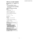
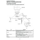
[7] Removing the Lamp unit, CW fan, Outlet Fan, Lamp duct, Lamp fan, Bimetal, Temp sensor
and Formatter unit.
and Formatter unit.
1. Remove the three screws and detach the Lamp unit.
2. Remove the two screws and detach the CW fan.
3. Remove the three screws and detach the Outlet fan.
4. Remove the two screws and detach the Lamp duct.
5. Remove the two screws and detach the Lamp fan.
6. Remove the two screws and detach the Bimetal.
7. Remove the seven screws and detach the Temp sensor and Formatter shield (Back).
8. Remove the four screws and detach the Formatter PWB and DMD.
9. Remove the two screws.
10.Remove the one screw and detach the Formatter shield (Front).
Lamp unit
CW fan
Outlet fan
Lamp duct
Lamp fan
Bimetal
Temp sensor
Formatter shield (Back)
Formatter shield (Front)
Formatter
shield (Back)
shield (Back)
Formatter PWB
7-1
7-2
7-3
7-4
7-5
7-6
7-9
7-10
7-8
7-7
Display

