Sharp XV-Z21000 (serv.man7) Service Manual ▷ View online
XV-Z20000/XV-Z21000/DT-5000
2 – 2
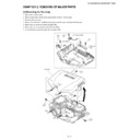
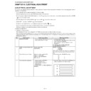
[2] Removing the Fans and PWB Unit Assembly
1. Disconnect the fourteen connectors.
2. Remove the two screws and detach the Lamp socket.
3. Remove the three screws and detach the Intake duct (upper). Detach the two Fans.
4. Remove the four screws and detach the PWB Unit Assembly.
5. Remove the three screws and detach the Intake duct (lower).
2-1
2-1
2-1
2-1
2-1
Intak
duct
(upper)
duct
(upper)
Fan
Fan
Intake duct
(lower)
2-2
2-3
2-5
2-5
2-5
2-4
[TB]
P9702
XV-Z20000/XV-Z21000/DT-5000
2 – 3
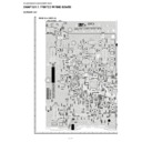
[3] Removing the Rear panel assembly, PC I/F PWB and the Main PWB
1. Remove the three screw.
2. Remove the two screws.
3. Remove the two screws.
4. Remove the four hexagonal supports and detach the Rear panel assembly.
5. Remove the four screws and detach the PC I/F assembly.
6. Remove the two screws and remove the four socket, and detach the shields.
7. Remove the one connector.
8. Remove the three screws and remove the two hexagonal supports.
9. Remove the one hook and detach the Main PWB.
3-5
3-6
3-7
3-8
3-8
3-9
3-1
3-2
3-3
3-4
3-4
PC I/F PWB
Rear panel assembly
hook
hook
lower shield
Upper shield
Socket
Socket
Main PWB
XV-Z20000/XV-Z21000/DT-5000
2 – 4
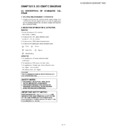
[4] Precaution on Mounting the PC I/F PWB
1. Insert the lower shield into the power supply unit.
2. Align the PC I/F PWB with the socket on the main PWB, and securely connect them by pressing the 3 socket sections from above.
3. Fit the upper shield to the lower shield.
NOTE: (1) You must pay attention to the fitting direction of the upper and lower shields (both sides). (Figures 1 and 2)
(2) The upper shield on the terminal side must not be placed on the PWB. (Figure 3)
4. Install the 2 screws (3-6).
5. Install the 4 screws (3-5).
The upper shield must be located the outer side.
The lower shield must be located
the outer side.
the outer side.
Upper shield
Lower shield
Figure 1
Hook
Hook
The lower shield must be located the outer side.
Upper shield
Lower shield
Hook
Hook
The upper shield must be located the outer side.
Figure 2
PC I/F PWB
Upper Shield
The upper shield must not be
placed on the PWB.
placed on the PWB.
Figure 3
XV-Z20000/XV-Z21000/DT-5000
2 – 5
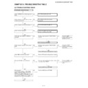
[5] Removing the Power unit shield assembly and Power/Ballast assembly
1. Remove the five screws and remove the two hooks, and detach the Power unit shield assembly.
2. Remove the one connector.
3. Remove the two screws and remove the two PWB Holders, and detach the Power/Ballast assembly.
NOTE: Order the Power/Ballast assembly when replacing the ballast unit.
5-1
5-1
5-1
5-1
5-2
5-3
5-3
5-1
Power unit shield
Assembly.
Assembly.
Ballast CTR
PWB
PWB
Power/
Ballast PWB
Ballast PWB
hook
hook
5-3
Display

