Sharp XV-Z21000 (serv.man3) Service Manual ▷ View online
XV-Z20000/XV-Z21000/DT-5000
5 – 9
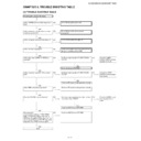
Check the input at the components
(480i and 576i are excluded).
(480i and 576i are excluded).
Supply a component signal to C1 or
C2. (Separate HV sync signal is not
connected.)
C2. (Separate HV sync signal is not
connected.)
Select C1 or C2 using the key on the
main unit or the remote control.
main unit or the remote control.
Is a projection image displayed?
NO
Go to "Check the SOG circuit.".
YES
Is the color normal?
NO
Perform the process adjustment.
Does the color become normal?
Does the color become normal?
NO
Go to “IC5652 peripheral check”.
YES
Is the image frame normal?
NO
Go to "IC5652 peripheral check".
YES
End.
Check the SOG circuit.
Is the signal generator (input source)
set correctly?
set correctly?
NO
Set the signal generator (input source)
correctly.
correctly.
YES
Is a composite synchronization signal
present at TL5513?
present at TL5513?
YES
The SOG circuit is normal.
NO
Is a composite synchronization signal
with the correct timing being output to
TL5511?
with the correct timing being output to
TL5511?
YES
The IC5514 peripheral circuit is defective.
NO
Is a video signal present at R5551?
YES
The SOG circuits (IC5512, IC5513 and
Q5570 - 09) are defective.
Q5570 - 09) are defective.
NO
The IC5209 peripheral circuit is
defective or the main unit is defective.
defective or the main unit is defective.
XV-Z20000/XV-Z21000/DT-5000
5 – 10
Check the 525i (625i) RGB (or com-
ponent) input.
ponent) input.
Supply a 525i (625i) RGB (or compo-
nent) signal to C1 or C2.
nent) signal to C1 or C2.
Select C1 or C2 using the key on the
main unit or the remote control.
main unit or the remote control.
Is a projection image displayed?
NO
Go to "Check the SOG circuit."
YES
Is the picture distorted?
NO
Go to "Check the VIDEO synchronization
signal."
signal."
YES
Is the color normal?
NO
Perform the process adjustment.
YES
Is the image frame normal?
NO
Go to "IC5652 peripheral check".
YES
END.
XV-Z20000/XV-Z21000/DT-5000
5 – 11
Check the composite VIDEO
(CVBS) input.
(CVBS) input.
Supply an NTSC3.58 VIDEO signal
to VIDEO.
to VIDEO.
Select VIDEO using the key on the
main unit or the remote control.
main unit or the remote control.
Is a projection image displayed?
Is the picture distorted?
Is the picture distorted?
NO
Go to "Check the VIDEO synchronization
signal."
signal."
YES
Is the color normal?
Is the image frame normal?
Is the image frame normal?
NO
Go to "IC5706 peripheral check".
YES
END.
Check the S-VIDEO input.
Supply an NTSC3.58 S-VIDEO signal
to S-VIDEO.
to S-VIDEO.
Select S-VIDEO using the key on the
main unit or the remote control.
main unit or the remote control.
Is a projection image displayed?
Is the picture distorted?
Is the picture distorted?
NO
Go to "Check the VIDEO synchronization
signal."
signal."
YES
Is the color normal?
Is the image frame normal?
Is the image frame normal?
NO
Go to "IC5706 peripheral check".
YES
END.
XV-Z20000/XV-Z21000/DT-5000
5 – 12
Check the
VIDEO syn-
chronization
signal.
VIDEO syn-
chronization
signal.
Is a vertical syn-
chronization sig-
nal present at
TL5710?
chronization sig-
nal present at
TL5710?
NO
Is a clock signal
(24.57 MHz)
present at
X5701?
(24.57 MHz)
present at
X5701?
Check the voltage
output of IC5702
and
IC5703.X5701 or
IC5706 is defec-
tive.
output of IC5702
and
IC5703.X5701 or
IC5706 is defec-
tive.
YES
NO
Is a horizontal
synchronization
signal present at
TL5711?
synchronization
signal present at
TL5711?
NO
YES
YES
The VIDEO syn-
chronization sig-
nal is normal.
chronization sig-
nal is normal.
Is a video signal
present at
TL5712?
present at
TL5712?
YES
IC5706 is defec-
tive.
tive.
NO
Is the input signal
525iRGB (or com-
ponent)?
525iRGB (or com-
ponent)?
YES
Is a video signal
present at
TL5703?
present at
TL5703?
YES
IC5706 is defec-
tive.
tive.
NO
NO
Check peripheral
circuits of Q5701
and Q5707.
The main unit is
defective.
circuits of Q5701
and Q5707.
The main unit is
defective.
Is the input signal
composite VIDEO
(CVBS)?
composite VIDEO
(CVBS)?
YES
Is a video signal
present at
TL5707?
present at
TL5707?
YES
Is S-VIDEO pro-
jected normally?
jected normally?
NO
IC5706 is defec-
tive.
tive.
NO
NO
YES
Check peripheral
circuits of Q5706
and Q5712.
The main unit is
defective.
circuits of Q5706
and Q5712.
The main unit is
defective.
Check peripheral
circuits of IC5707.
circuits of IC5707.
Is the input signal
S-VIDEO?
S-VIDEO?
YES
Are video signals
sent to TL5705
and TL5706?
sent to TL5705
and TL5706?
YES
IC5706 is defec-
tive.
tive.
NO
Check peripheral
circuits of Q5704,
Q5705, Q5710
and Q5711.
The main unit is
defective.
circuits of Q5704,
Q5705, Q5710
and Q5711.
The main unit is
defective.
Click on the first or last page to see other XV-Z21000 (serv.man3) service manuals if exist.

