Sharp XV-Z200E (serv.man8) Service Manual ▷ View online
18
XV-Z200U/E, XV-Z201E
DT-300
DT-300
*1057-6bbc
CHXXXX
LLLLL
YYYYYYY
L LLL LM
TI Intemal Numbering
TI Intemal Numbering
2-Dimensional Matrix Code
(DMD Part Number and
Serial Number)
Part 1 of Serial Number
(7 characters)
Part 2 of Serial Number
(6 or7 characters)
DMD Part Number
1
The last alphabet letter indicates the
Bin voltage setting (B~E).
2
Set these two switches.
3
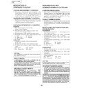
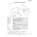
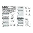
* Precautions in setting up the DMD (Digital Micromirror Device) unit
Before connecting the formatter PWB to the optical engine, take the following steps. Look at the voltage rank marking
that is on the DMD itself. Referring to this marking, set the DIP switches on the formatter PWB. And connect this PWB
DMD Setting: Check the last alphabet character shown in
1
, and set the two switches shown in
2
according to the
configurations shown in
3
.
Set the formatter PWB switches according to the Bin voltage shown on the back face of the DMD.
Display

