Sharp XV-Z12000 (serv.man7) Service Manual ▷ View online
9
XV-Z12000
Operation Manual
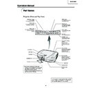
Adjustment b uttons
(", ', \, |)
For selecting menu items.
ENTER butto n
For setting items selected
or adjusted on the menu.
UNDO button
For undoing an operation or
returning to the default
settings.
Lens shift dial
Zoom knob
Focus ring
MENU bu tton
For displaying adjustment
and setting screens.
and setting screens.
RESIZE bu tton
For switching the screen
size (SIDE BAR, SMART
STRETCH, etc.).
For switching the screen
size (SIDE BAR, SMART
STRETCH, etc.).
INPUT butto n
For switching input mode
1, 2, 3, 4 or 5.
1, 2, 3, 4 or 5.
ON bu tton
For turning the power on.
For turning the power on.
STANDBY bu tton
For putting the projector
into the standby mode.
For putting the projector
into the standby mode.
Temperature warning
indicator
indicator
When the internal
temperature rises, this
indicator will illuminate
red.
temperature rises, this
indicator will illuminate
red.
Lamp indicator
Illuminates blue, indicating
normal function. Replace
the lamp when the
indicator illuminates red.
normal function. Replace
the lamp when the
indicator illuminates red.
Power indicator
Illuminates red, when the
projector is in standby.
When the power is turned
on, this indicator will
illuminate blue.
projector is in standby.
When the power is turned
on, this indicator will
illuminate blue.
Adjustment f oot
Lens cap
Intake vent
Adjustment foot
Remote control
sensor
sensor
Projector (Front and Top View)
rt Names
Attaching and removing the lens cap
• Press on the two buttons of the lens cap
• Press on the two buttons of the lens cap
and attach it on the lens. Then release
the buttons to lock it in place.
the buttons to lock it in place.
• Press on the two buttons of the lens cap
and remove it from the lens.
In this operation manual, the illustration and the
screen display are simplified for explanation,
and may differ slightly from actual display.
screen display are simplified for explanation,
and may differ slightly from actual display.
10
XV-Z12000
3
2
1
1
3
Remote control
sensor
Kensington Security
Standar d connector
INPUT 2 terminals
Terminals for
component and RGB
signals.
INPUT 5 terminal
Terminal for DVI
digital, computer
RGB and component
signals.
INPUT 1 terminals
Terminals for
component and
RGB signals
.
INPUT 3 terminal
Terminal for
connecting video
equipment with an
S-video terminal.
connecting video
equipment with an
S-video terminal.
WIRED REMOTE
cont ro l input
terminal
cont ro l input
terminal
INPUT 4 terminal
For connecting
video equipment.
video equipment.
Intake vent
Rubber cap
The terminal cover can be attached
after removing the rubber cap.
after removing the rubber cap.
DC 12V OUTPUT
terminal
terminal
RS-232C terminal
For controlling
projector using a
computer.
projector using a
computer.
AC soc ket
Exhaust vent
Intake vent
Projector (Rear View)
Using the Kensington Lock
This projector has a Kensington Security Standard connector for use with a Kensington MicroSaver Security Sys-
tem. Refer to the information that came with the system for instructions on how to use it to secure the projector.rr
tem. Refer to the information that came with the system for instructions on how to use it to secure the projector.rr
Using the Terminal
T
T
Cover
When the projector is used on a desktop, high mounted or
ceiling mounted, attach the terminal cover (supplied) to hide
the connecting cables.
Attaching the Terminal
ceiling mounted, attach the terminal cover (supplied) to hide
the connecting cables.
Attaching the Terminal
T
T
Cover
1 Align the hook on the terminal cover with the insert hole
in the hook at the back of the projector.
2 Press the hook in the direction indicated with the arrow to
fasten the terminal cover to the projector.
3 Insert the terminal cover into the mounting groove on the
projector while pushing the tabs inside the terminal cover
to the outside with your fingers.
to the outside with your fingers.
Removing the rubber cap attached on the pro-
jector and attach the clips.
jector and attach the clips.
11
XV-Z12000
Remote Control (Front View)
Names
KEYSTONE button
For adjusting Keystone Correction
or Vertical Size setting.
WIRED R/C JACK
For controlling the projector by
connecting the remote control to the
projector.
connecting the remote control to the
projector.
ON button
For turning the power on.
MENU button
For displaying adjustment and
setting screens.
setting screens.
Adjustment buttons
(", ', \, |)
(", ', \, |)
For selecting menu items.
ENTER button
For setting items selected or
adjusted on the menu.
UNDO button
For undoing an operation or
returning to the default settings.
INPUT buttons
For switching to the respective
input modes.
input modes.
RGB/COMP. button
For switching to the respective
input signal type.
AUTO SYNC button
For automatically adjusting images
when connected to a computer.
Remote control signal transmitters
RESIZE button
For switching the screen size
(SIDE BAR, SMART STRETCH,
etc.).
(SIDE BAR, SMART STRETCH,
etc.).
PICTURE POSITION button
For selecting the picture position.
STANDBY b utton
For putting the projector into the
standby mode.
IRIS button
For switching “HIGH BRIGHTNESS
MODE”, “MEDIUM MODE”
and “HIGH CONTRAST MODE”.
MODE”, “MEDIUM MODE”
and “HIGH CONTRAST MODE”.
Backlight button
For lighting all buttons on
the remote control.
For lighting all buttons on
the remote control.
Remote Control (Top View)
12
XV-Z12000
45˚
30˚
30˚
45˚
30˚
23'(7 m)
ing the Remote Control
The remote control can be used to control the projector
within the ranges shown in the illustration.
within the ranges shown in the illustration.
Note
• The signal from the remote control can be reflected off a screen
for easy operation. However, the effective distance of the signal
may differ due to the screen material.
may differ due to the screen material.
When using the remote control:
• Be sure not to drop, expose to moisture or high temperature.
• The remote control may malfunction under a fluorescent lamp.
• The remote control may malfunction under a fluorescent lamp.
Under that circumstance, move the projector away from the fluo-
rescent lamp.
rescent lamp.
Inserting the Batteries
The batteries (used is two "AA" size.)
Incorrect use of the batteries may cause them to leak or explode. Please follow the precautions below .
Caution
• Insert the batteries making sure the polarities correctly match the
and
marks inside the battery compart-
ment.
• Batteries of different types have different properties, therefore do not mix batteries of different types.
• Do not mix new and old batteries.
• Do not mix new and old batteries.
This may shorten the life of new batteries or may cause old batteries to leak.
• Remove the batteries from the remote control once they have run out, as leaving them can cause them to leak.
Battery fluid from leaked batteries is harmful to your skin, therefore be sure to first wipe them and then remove
them using a cloth.
them using a cloth.
Remote control
Available Range of the Remote Control
Remote control
Display

