Sharp XV-C2E (serv.man4) Service Manual ▷ View online
XV-C2E
24
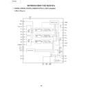
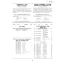
INTRODUCING THE NEW ICs
1. IC4203, IC4204, IC4205 (VHiCXD1176Q-1) A/D Converter
1) Block Diagram
28
30
31
1
4
5
6
7
8
10
11
12
9
32
DV
SS
OE
D0(LSB)
D1
D2
D3
D4
D5
D6
D7(MSB)
DV
DD
DV
DD
CLK
NC
NC
DV
SS
2
3
29
27
26
CLE
CCP
VREF
13
14
15
M·M
SEL
Sync
PW
16
17
18
19
20
21
22
23
24
25
AV
DD
VRTS
VRT
AV
DD
AV
DD
V
IN
AV
SS
AV
SS
VRB
VRBS
–
+
Clock generator
Lower
data
latch
data
latch
Upper
data
latch
data
latch
Upper encoder
(4 BIT)
(4 BIT)
Lower encoder
(4 BIT)
(4 BIT)
Lower encoder
(4 BIT)
(4 BIT)
Lower sampling
comparator (4 BIT)
comparator (4 BIT)
Lower sampling
comparator (4 BIT)
comparator (4 BIT)
Upper sampling
comparator (4 BIT)
comparator (4 BIT)
Reference supply
XV-C2E
25
2) Terminals
Terminal
Symbol
Remarks
NO.
Terminal
Symbol
Remarks
NO.
1~8
D0~D7
D0(LSB) - D7(MSB) output
9, 32
NC
NC pin
10, 11
DV
DD
Digital +5V
12
CLK
Clock input
13
SEL
At SEL=Low, the monomulti-vibrator gen-
erates clamp pulse, triggered by the trail-
ing edge of sync input at No.14 terminal.
erates clamp pulse, triggered by the trail-
ing edge of sync input at No.14 terminal.
At SEL=High, the monomulti-vibrator
generates clamp pulse, triggered by the
leading edge of sync input at No.14 ter-
minal.
generates clamp pulse, triggered by the
leading edge of sync input at No.14 ter-
minal.
14
Sync
Trigger pulse input to the monomulti-vi-
brator.
Trigger polarity can be selected by No.13
(SEL) terminal.
brator.
Trigger polarity can be selected by No.13
(SEL) terminal.
15
PW
When clamp pulse is generated by the
monomulti-vibrator.:
• Pulse width is determined by external
monomulti-vibrator.:
• Pulse width is determined by external
R and C.
When clamp pulse is directly inputted.:
• Clamp pulse is inputted to No.15 (PW)
• Clamp pulse is inputted to No.15 (PW)
terminal. The signal voltage of low level
is clamped. (No.14 (Sync) terminal is
fixed at High or Low at this time.)
is clamped. (No.14 (Sync) terminal is
fixed at High or Low at this time.)
16,19,20
AV
DD
Analog +5V
17
VRTS
If this terminal is short-circuited with the
VTR terminal, it generates the voltage of
about +2.6V.
VTR terminal, it generates the voltage of
about +2.6V.
18
VRT
Reference voltage (Top)
24
VRB
Reference voltage (Bottom)
21
V
IN
Analog input
22,23
AV
SS
Analog ground
25
VRBS
If this terminal is short-circuited with the
VRB terminal, it generates the voltage
of about +0.5V.
VRB terminal, it generates the voltage
of about +0.5V.
26
VREF
Terminal for input of clamp reference volt-
age.
age.
It clamps pulse so that the reference volt-
age and the input signal of clamp sec-
tion are equal to each other.
age and the input signal of clamp sec-
tion are equal to each other.
27
CCP
Terminal to integrate clamp control volt-
age.
age.
Change in CCP voltage and Vin voltage
are in the relation of normal phase.
are in the relation of normal phase.
28, 31
DV
SS
Digital ground.
29
CLE
When CLE=Low, clamp function be-
comes effective.
comes effective.
When CLE=High, clamp function be-
comes ineffetive, and only the usual A/D
converter function becomes effective.
comes ineffetive, and only the usual A/D
converter function becomes effective.
Clamp pulse can be counted by connect-
ing the CLE terminal to DVdd with a sev-
eral-hundred-ohm resistor in between.
ing the CLE terminal to DVdd with a sev-
eral-hundred-ohm resistor in between.
30
OE
When OE=Low, the data is outputted.
When OE=High, terminals D0 - D7 be-
comes at high impedance.
comes at high impedance.
XV-C2E
26
2. IC4206, IC4207, IC4208 (VHiPD485505-2) Line memory
1) Terminal Connection Diagram (Marking Side)
8
9
10
11
12
7
RCK
GND
6
5
4
RSTR
RE
D
OUT6
D
OUT5
D
OUT4
D
OUT7
D
OUT3
3
D
OUT2
2
D
OUT1
1
17
16
15
14
13
18
19
20
21
22
23
24
D
OUT0
WCK
V
CC
RSTW
WE
D
IN6
D
IN5
D
IN4
D
IN7
D
IN3
D
IN2
D
IN1
D
IN0
D
IN0
~D
IN7
D
OUT0
~D
OUT7
WCK
RCK
WE
RE
RSTW
RSTR
V
CC
GND
: Data input
: Data output
: Write clock input
: Read clock input
: Write enable input
: Read enable input
: Reset write input
: Reset read input
: +5V power
: Ground
XV-C2E
27
2) Block Diagram
D
IN0
D
IN1
D
IN2
D
IN3
D
IN4
D
IN5
D
IN6
D
IN7
WE
RSTR
RCK
D
OUT0
D
OUT1
D
OUT2
D
OUT3
D
OUT4
D
OUT5
D
OUT6
D
OUT7
RE
RSTW
V
CC
GND
Write Address Pointer
40,384 bits
(5,048 by 8)
Memory Cell Array
Output Buffer
Input Buffer
WCK
Read Address Pointer

