Sharp XG-NV5XE (serv.man46) Service Manual ▷ View online
14
XG-NV5XE
XG-NV5XM
XG-NV5XM
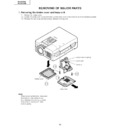
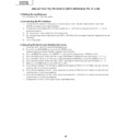
5. Removing the optical mechanism unit
5-1. Remove the six optical mechanism unit lock screws. Lift the unit off the position.
6. Removing the ballast unit and inlet unit
6-1. Disconnect the connector (PA) from the inlet unit. Take out the AC power switch.
6-2. Pull the inlet unit toward yourself off the position.
Note: Before installing the lamp cover, make sure the AC power switch is at the " " (OFF) position.
6-2. Pull the inlet unit toward yourself off the position.
Note: Before installing the lamp cover, make sure the AC power switch is at the " " (OFF) position.
(PA)
(BA)
(PA)
5-1
6-1
6-2
(FG)
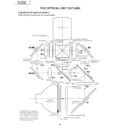
Optical Mechanism Unit
Duct Fan Unit
AC power switch
(for Lamp replacement)
(for Lamp replacement)
Cover
Inlet Unit
Display

