Sharp XG-NV51XE (serv.man9) Service Manual ▷ View online
27
XG-NV51XE/XM/XA
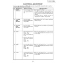
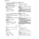
100% White Red
100% White Red
No.
Adjusting point
Adjusting conditions
Adjusting procedure
19
PAL colour
saturation level
saturation level
1. Feed the PAL colour bar
signal.
Group : VIDEO 1
Subject : P-COLOR
Group : VIDEO 1
Subject : P-COLOR
2. Connect the oscilloscope to
pin (1) of P801.
»
Using the control switches or the remote controller
buttons, adjust the difference between the 100%
white portion and the red portion to 0.20 ±0.02 Vp-p.
buttons, adjust the difference between the 100%
white portion and the red portion to 0.20 ±0.02 Vp-p.
20
SECAM colour
saturation level
saturation level
1. Feed the SECAM colour
bar signal.
Group : VIDEO 1
Subject : S-COLOR
Group : VIDEO 1
Subject : S-COLOR
2. Connect the oscilloscope to
pin (1) of P801.
»
Using the control switches or the remote controller
buttons, adjust the data to have a level difference of
0.25 ±0.02 Vp-p between the 100% white portion
and the red portion.
buttons, adjust the data to have a level difference of
0.25 ±0.02 Vp-p between the 100% white portion
and the red portion.
21
Video white
balance
balance
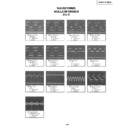
1. Feed the NTSC mono-
scope pattern signal
Group : VIDEO 2
Subject : R1-GAIN
Group : VIDEO 2
Subject : R1-GAIN
B1-GAIN
»
Using the control switches or the remote controller
buttons, adjust so that the entire screen looks
evenly colourless.
buttons, adjust so that the entire screen looks
evenly colourless.
22
Colour
irregularity
correction
position
irregularity
correction
position
1. Feed the gray-only RGB
colour signal.
2. Find the colour irregularity
position on the screen.
3. Group
: NOKO
Subject : NOKO-RL
4. Group : NOKO
Subject : NOKO-LH
»
If the colour is irregular, adjust the NOKO-RL data.
Set it to R for the right-hand colour irregularity and
to L for the left-hand one.
Set it to R for the right-hand colour irregularity and
to L for the left-hand one.
»
When there is no colour irregularity, turn off the saw-
tooth waveform correction on the NOKO-LH data.
tooth waveform correction on the NOKO-LH data.
23
Colour
irregularity
correction gain
(in case of
colourirregularity)
irregularity
correction gain
(in case of
colourirregularity)
1. Feed the gray-only RGB
colour signal.
»
Adjust R4215 to minimize the right-hand and left-
hand colour irregularity.
hand colour irregularity.
28
XG-NV51XE/XM/XA
No.
Adjusting point
Adjusting conditions
Adjusting procedure
24
1. Receive the colour bar sig-
nal.
»
In the process mode and select L1. Check the col-
our and tint.
our and tint.
26
»
In the process mode nad select L3. Check the bass,
treble and balance.
treble and balance.
25
1. Receive the monoscope
pattern signal.
»
In the process mode and select L2. Check the pic-
ture, brightness and sharpness.
ture, brightness and sharpness.
27
RGB
performance
check
performance
check
1. Receive the RGB signal.
»
In the process mode and select L4. Check the pic-
ture, brightness, red, blue, clock, phase, horizontal
position, and vertical position.
ture, brightness, red, blue, clock, phase, horizontal
position, and vertical position.
28
Off-timer
performance
check
performance
check
»
In the process mode and select OFF. Make sure that
the off-timer starts with “5” (minutes), counts down
each minute in 1 second, and turns off the set at “0”.
the off-timer starts with “5” (minutes), counts down
each minute in 1 second, and turns off the set at “0”.
29
Thermistor
performance
check
performance
check
1. Heat the thermistor using a
dryer.
»
Make sure the “TEMP” is displayed.
31
IrDA
performance
check
performance
check
»
Make sure the IrDA signal can be received.
30
Automatic
synchronization
synchronization
1. Receive the PHASE check
pattern signal.
»
Call the VGA/S-VGA/XGA/SXGA mode and make
sure that the clock, phase, horizontal and vertical
positions can be automatically adjusted.
sure that the clock, phase, horizontal and vertical
positions can be automatically adjusted.
32
Keystone
correction
performance
check
correction
performance
check
»
Make sure the keystone correction functions well.
33
Factory settings
»
Make the following settings.
S4
“Factory setting 4”
Remote controller
setting
setting
Process
adjustment
adjustment
28
XG-NV51XE/XM/XA
No.
Adjusting point
Adjusting conditions
Adjusting procedure
24
1. Receive the colour bar sig-
nal.
»
In the process mode and select L1. Check the col-
our and tint.
our and tint.
26
»
In the process mode nad select L3. Check the bass,
treble and balance.
treble and balance.
25
1. Receive the monoscope
pattern signal.
»
In the process mode and select L2. Check the pic-
ture, brightness and sharpness.
ture, brightness and sharpness.
27
RGB
performance
check
performance
check
1. Receive the RGB signal.
»
In the process mode and select L4. Check the pic-
ture, brightness, red, blue, clock, phase, horizontal
position, and vertical position.
ture, brightness, red, blue, clock, phase, horizontal
position, and vertical position.
28
Off-timer
performance
check
performance
check
»
In the process mode and select OFF. Make sure that
the off-timer starts with “5” (minutes), counts down
each minute in 1 second, and turns off the set at “0”.
the off-timer starts with “5” (minutes), counts down
each minute in 1 second, and turns off the set at “0”.
29
Thermistor
performance
check
performance
check
1. Heat the thermistor using a
dryer.
»
Make sure the “TEMP” is displayed.
31
IrDA
performance
check
performance
check
»
Make sure the IrDA signal can be received.
30
Automatic
synchronization
synchronization
1. Receive the PHASE check
pattern signal.
»
Call the VGA/S-VGA/XGA/SXGA mode and make
sure that the clock, phase, horizontal and vertical
positions can be automatically adjusted.
sure that the clock, phase, horizontal and vertical
positions can be automatically adjusted.
32
Keystone
correction
performance
check
correction
performance
check
»
Make sure the keystone correction functions well.
33
Factory settings
»
Make the following settings.
S4
“Factory setting 4”
Remote controller
setting
setting
Process
adjustment
adjustment
Display

