Sharp XG-F315X (serv.man4) Service Manual ▷ View online
PG-F310X/XG-F315X
4 – 1
XGF315X
Service Manual
CHAPTER 4.
ELECTRICAL ADJUSTMENT
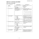
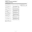
[1] ELECTRICAL ADJUSTMENT
No.
Adjusting point
Adjusting conditions
Adjusting procedure
1
EEPROM
initialization
initialization
1) Turn on the power (with the lamp on) and
warm up the set for 15 minutes.
• Make the following settings.
Press S2551 to call the process mode and execute
“SS2” on SS menu.
Press S2551 to call the process mode and execute
“SS2” on SS menu.
2
Model setting
(Process menu)
1) Select the following group and subject.
1) Select the following group and subject.
Group: CONFIRM
Subject: MODEL
Subject: MODEL
1) Check the fixed value.
PG-F310X: 0
XG-F315X: 0
XG-F315X: 0
3
Adjustment of CW index
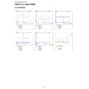
1) Signal input: Send 256 STEP color bar.
XGA series (XGA60HZ)
2) Select the following group and subject.
Group: ADJUST CW/Auto KS
Subject: CW-INDEX.
Subject: CW-INDEX.
1) The signal is input into computer 1.
2) Select the adjustment item and adjust the lamp
2) Select the adjustment item and adjust the lamp
gradation patterns of RGBW so that smooth pat-
terns without noise appear.
terns without noise appear.
4
R/G/B contrast adjustment
(manual or automatic)
(manual or automatic)
1) Select the following group and subjects.
Group: ADJUST
AD/DLP
Subject: R-CONT
G-CONT
B-CONT
(Process GAMMA interlock)
AD/DLP
Subject: R-CONT
G-CONT
B-CONT
(Process GAMMA interlock)
2) Amplitude level 96% (0.67Vpp) the signal
is input into computer 1.
XGA series (XGA60HZ)
XGA series (XGA60HZ)
1) Measure chromaticity of the 96% white wind pat-
tern using CA100.
2) On the screen where bit dropouts occur, raise the
values of R/G/B-Contrast. Adjust the values so that
bright red, green, and blue bit dropouts appear on
a black background; and amounts of change in x
value of R and y values of G/B become 100/1000
or more.
bright red, green, and blue bit dropouts appear on
a black background; and amounts of change in x
value of R and y values of G/B become 100/1000
or more.
3) If adjustment is performed manually watching the
screen, make adjustment so that bright red, green,
and blue bit dropouts appear on more than half of
the screen.
and blue bit dropouts appear on more than half of
the screen.
5
RGB white balance adjustment
1) 50% gray pattern signal is input into com-
puter 1.
XGA series (XGA60HZ)
XGA series (XGA60HZ)
2) Select the following group and subjects.
Group: ADJUST
AD/DLP
Subject: R-GAIN
G-GAIN
B-GAIN
AD/DLP
Subject: R-GAIN
G-GAIN
B-GAIN
1) Raise the values of two of R/G/B-GAIN (default:
100) so that the following chromaticity values are
obtained using CL200.
x value: 305
obtained using CL200.
x value: 305
± 5
y value: 323
± 5
6
sRGB white balance adjustment
1) 50% gray pattern signal is input into com-
puter 1.
XGA series (XGA60HZ)
XGA series (XGA60HZ)
2) Select the following group and subjects.
Group: CONFIRM/DLP
Subject: S-G-OS
S-B-OS
Subject: S-G-OS
S-B-OS
1) Adjust S-G-OS and S-B-OS so that the following
chromaticity values are obtained using CL200.
x value: 313
x value: 313
± 5
y value: 329
± 5
7
Auto keystone initialization
and audio output check
and audio output check
Select the following group and subjects.
Group : ADJUST
CW/Auto KS
Subject : CAL
Group : ADJUST
CW/Auto KS
Subject : CAL
1) With the set placed on a level surface, press the
ENTER key and check that K-SENS value is 0
±3.
Check that keystone is caused by tilting the unit.
2) Check that the start-up sound is heard from the
speaker when the ENTER key is pressed.
R
G
B
G
B
W
PG-F310X/XG-F315X
4 – 2
Check items
No.
Adjusting point
Adjusting conditions
Adjusting procedure
1
Adjustment of RGB brightness
1) Select the following group and subjects.
Group: CONFIRM/AD
Subject: R-BRIGHT
G-BRIGHT
B-BRIGHT
(Process GAMMA interlock)
Subject: R-BRIGHT
G-BRIGHT
B-BRIGHT
(Process GAMMA interlock)
1) Check the fixed value.
Fixed value: 125
2
Adjustment of Component offset
1) Feed 10-step signal with 480P compo-
nent 100% amplitude.
2) Select the following group and subjects.
Group: CONFIRM/AD
Subject: C-R-OS
C-B-OS
(Process GAMMA interlock)
Subject: C-R-OS
C-B-OS
(Process GAMMA interlock)
1) Check the fixed value.
C-R-OS: 260
C-B-OS: 260
C-B-OS: 260
3
Adjustment of DLP Brightness
1) Select the following group and subject.
Group: CONFIRM/DLP
Subject: R-BLK
G-BLK
B-BLK
(Process GAMMA interlock)
Subject: R-BLK
G-BLK
B-BLK
(Process GAMMA interlock)
1) Check the fixed value.
Fixed value: 252
4
Video Contrast adjustment
1) Feed NTSC 100% wind pattern signal.
(Signal with burst)
2) Select the following group and subjects.
Group: CONFIRM/VIDEO
Subject: V-CONT
Subject: V-CONT
1) Check the fixed value.
Fixed value: 134
5
Adjustment of Video Brightness
1) Feed NTSC 100% wind pattern signal.
(Signal with burst)
2) Select the following group and subject.
Group: CONFIRM/VIDEO
Subject: V-BRIGHT
Subject: V-BRIGHT
1) Check the fixed value.
Fixed value: 68
6
Adjustment of Video Tint
1) Feed split color bar.
2) Select the following group and subject.
2) Select the following group and subject.
Group: CONFIRM/VIDEO
Subject: V-HUE
Subject: V-HUE
1) Check the fixed value.
Fixed value: 128
7
Adjustment of Video color satura-
tion
tion
1) Select the following group and subject.
Group: CONFIRM/VIDEO
Subject: V-COLOR
Subject: V-COLOR
1) Check the fixed value.
Fixed value: 139
8
RGB tone reproduction adjust-
ment
ment
1) Feed the SMPTE pattern signal.
1) Make sure the 100% and 95% white as well as the
0% and 5% black gradations are visible.
9
VIDEO white balance adjustment
1) Feed the 50% gray signal.
2) Select the following group and subjects.
2) Select the following group and subjects.
Group: CONFIRM/VIDEO
Subject: V-R-OS
V-G-OS
V-B-OS
Subject: V-R-OS
V-G-OS
V-B-OS
1) V-R-OS is 123.
V-G-OS is 123.
V-B-OS is 123.
V-B-OS is 123.
10
White balance checking and
readjustment
readjustment
1) RGB Input
sRGB Input
VIDEO Input
DTV Input
DVD Input
VIDEO Input
DTV Input
DVD Input
1) Check that there is no deviation of white balance
with the monitor.
11
Off-timer performance
1) Select the following group and subjects.
Group: CONFIRM/CHECK
Subject: TEMP-OFF
Subject: TEMP-OFF
1) Select OFF from the process mode.
Make sure the off-timer starts with 5 minutes
onscreen and count one minute in one second.
And then indication is 0 minute, the power supply
of the set is cut off.
onscreen and count one minute in one second.
And then indication is 0 minute, the power supply
of the set is cut off.
12
Thermistor performance checking 1) Heat the thermistor with a hair dryer.
1) Make sure that the temperature is indicated.
13
Auto sync performance checking
1) Feed the phase check pattern signal.
1) In the VGA, SVGA, XGA and SXGA modes, make
sure the Clock, Phase, H-Pos and V-Pos settings
can be automatically adjusted.
can be automatically adjusted.
PG-F310X/XG-F315X
4 – 3
* Writing a software program (before main PWB is mounted)
Use the DLP Composer Lite Ver. 7.0 or higher to download the firmware.
* “Skip Boot Loader Area” set to “32KB”
After writing the specified version of firmware to the PWB using the RS232C cable, check the version of the written firmware.
If no software program is written, all three LEDs light up in the chassis inspection process.
Calling and quitting the process mode with the control keys on this model.
* Although it is possible for the process OUT to exit using the process menu, the IN/OUT toggle command is also available considering the existing
specification.
1) Calling and quitting
With the menu not displayed, press the “ENTER”, “ENTER”, “VOL+”, “VOL-”, “ENTER”, ”ENTER” and “MENU” keys on the remote control or on
the main unit.
the main unit.
2) Others
Press the S2551 process key (toggle) on the main PWB to call and quit the process menu.
NOTE: When adjusting in the process mode, set a signal with a vertical frequency of 60 Hz or no signal. (May not be properly adjusted with other sig-
nals.)
Resetting the lamp timer for this model
1) Resetting procedure
In Stand-by, run this command to clear the operating time of the lamp to 0 and turn on the power.
Press and hold “ ”, “ENTER”, and “MENU”, and then press the “STANDBY/ON” key of the set.
Forced disabling of the System-Lock of this model
1) Disabling procedure
With System-Lock input window onscreen, press the “MENU”, “ENTER”, “ENTER”, “MENU”, “ENTER”, “ENTER” and “MENU” keys, in this order,
on the remote controller.
on the remote controller.
14
DVI input operation check
1) Send the video signal to the DVI terminal. 1) Check that an image is properly projected through
the digital input and analog input.
15
Monitor out check
1) Send signals to COMPUTER 1 and
COMPUTER 2.
2) Connect another monitor to the monitor
out.
3) Connect the audio OUT.
1) Check that the same images as seen on the
screen appear on the connected monitor and that
the sound from the sound source connected to the
audio OUT is heard.
the sound from the sound source connected to the
audio OUT is heard.
16
RS232C operation check
1) Connect the unit and a PC with the
RS232C cable.
1) Send a command from the PC, and check it func-
tions correctly.
17
USB operation check
1) Connect to a PC with an USB cable.
1) Check that page up/down is enabled using the
remote control.
18
Model name and version check
1) Select the following group.
Group: INFO/VERSION.
1) The model name appears in the MODEL field, and
the firmware version in the VERSION field.
Check that they are correct.
Check that they are correct.
19
LAN operation check (XG-F315X
only)
only)
1) Connect to a PC with a LAN cable.
1) Check that communication is possible.
20
Delivery settings
1) Make the following settings.
No.
Adjusting point
Adjusting conditions
Adjusting procedure
Destination
Process
Remote control
adjustment
adjustment
USA
SS4
Factory setting at 4
China
SS6
Factory setting at 6
Others
SS3
Factory setting at 3
PG-F310X/XG-F315X
4 – 4
[2] Adjustment mode process menu
1st Layer
2nd Layer
Default
ADJUST
CW/Auto KS
CW-INDEX
30
CAL
K-SENS
K-SENS
(0)
AD/DLP
R-CONT
110
G-CONT
110
B-CONT
110
R-GAIN
100
G-GAIN
100
B-GAIN
100
SS
SS1
—
SS2
—
SS3
—
SS4
—
SS5
—
SS6
—
CONFIRM
AD
R-BRIGHT
125
G-BRIGHT
125
B-BRIGHT
125
C-R-OS
260
C-B-OS
260
DLP
R-BLK
252
G-BLK
252
B-BLK
252
S-R-OS
128
S-G-OS
128
S-B-OS
128
VIDEO
V-CONT
134
V-BRIGHT
68
V-COLOR
139
V-HUE
128
V-R-OS
123
V-G-OS
123
V-B-OS
123
OFFSET-MODE
0
OFFSET-CONT
0
OFFSET-BRI
0
MODEL
MODEL-SELECT
0
CHECK
LED-CHK
0
TEMP-OFF
—
INFO
VERSION
MODEL
—
VER.
—
PATTERN
RGB
1
RGB50
1
CORSS
1
STEP
1
COLOR
1
CHR
1
INDEX
1
LAMP
CURRENT
0
HISTORY1
0
HISTORY2
0
HISTORY3
0
HISTORY4
0
TOTAL
0
TEMP/FAN
TEMP1
—
TEMP2
—
FAN0
3
FAN1
3
FAN2
3
1st Layer
2nd Layer
Default
OTHER
SPECIAL
USB-MODE
0
HDCP-MODE
0
PULSE-MODE
0
EDID
EEP-SELECT
1
EEP-WP
0
EXIT
Display

