Sharp XG-C50XE (serv.man11) Service Manual ▷ View online
39
XG-C50X
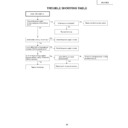
TROUBLE SHOOTING TABLE for PC I/F UNIT (Continued)
IC8025 or IC8013 is defective.
Go to "Checking of Sync Signal".
Is there the signal at pin (55) of
SC8002 (B-to-B connector)?
SC8002 (B-to-B connector)?
Somewhere in the signal route is
defective. Check the capacitors
and resistors between SC8002
and IC8013.
defective. Check the capacitors
and resistors between SC8002
and IC8013.
Make "Confirmation of Input
Signal Setting".
Signal Setting".
Is there the video signal at the land
of C8070?
of C8070?
Yes
No
Yes
Confirmation of Video Input
The signal source or connector is
defective.
defective.
End
Is the right item selected from input
menu?
menu?
Are the connectors connected
correctly?
correctly?
Yes
No
Yes
Confirmation of Input Signal
Setting
Setting
Select the right item.
2
No
Connect the connectors correctly.
1
No
40
XG-C50X
TROUBLE SHOOTING TABLE for PC I/F UNIT (Continued)
Is there the horizontal sync signal
at TL8130?
at TL8130?
Is there the vertical sync signal at
TL8131?
TL8131?
Make confirmation of input signal
setting.
setting.
R997, R996, SC8002 or their
periphery is defective.
periphery is defective.
Is there the vertical sync signal at
pin (11) of IC8363?
pin (11) of IC8363?
Is there the horizontal sync signal
at pin (5) of IC8363?
at pin (5) of IC8363?
Yes
Yes
Yes
Are both the vertical and horizontal
sync signals in appropriate timing?
sync signals in appropriate timing?
Yes
Is the signal generator
(input source) appropriate?
(input source) appropriate?
No
R997, R996, SC8002 or their
periphery is defective.
periphery is defective.
Yes
No
IC8363 is defective.
The sync signals are as specified.
End of checking.
End of checking.
No
Yes
No
No
No
Checking of Sync Signal
Set the signal source
appropriately.
appropriately.
2
41
XG-C50X
TROUBLE SHOOTING TABLE for PC I/F UNIT (Continued)
No
Yes
Yes
Yes
Checking of R, G and B Signals
Is the signal type set to RGB?
Set the signal type to RGB.
No
No
Set the process mode.
Select R, G and B individually on
the pattern menu.
the pattern menu.
Go to "Checking of GA4 and Its
Periphery".
Periphery".
For checking the input signal, set
the signal generator to gradation
signal.
the signal generator to gradation
signal.
Measure the signals at TL8169,
TL8170 and TL8180 on the
oscilloscope. (MSB bit after A/D
conversion)
TL8170 and TL8180 on the
oscilloscope. (MSB bit after A/D
conversion)
Are there the specified signals at
TL8169, TL8170 and TL8180?
TL8169, TL8170 and TL8180?
Does the signal come to C8062,
C8070 and C8078?
C8070 and C8078?
Go to "Confirmation of Video Input".
IC8013 or its periphery is defective.
IC8025 or its periphery is defective.
42
XG-C50X
TROUBLE SHOOTING TABLE for PC I/F UNIT (Continued)
No
No
Yes
Yes
Yes
Yes
Yes
No
Yes
No
No
No
Checking of GA4 and Its Periphery
Select R, G and B individually on
the pattern menu in the process
mode.
the pattern menu in the process
mode.
Is picture outputted appropriately
in R, G and B?
in R, G and B?
Checking of GA4 and its periphery
ends.
ends.
Measure the signals at pins (54),
(66) and (78) of SC8001 on the
oscilloscope. These signals are
MSB of B/G/R/.
(66) and (78) of SC8001 on the
oscilloscope. These signals are
MSB of B/G/R/.
Do the oscilloscope-measured
signals match with those selected
on the pattern menu?
signals match with those selected
on the pattern menu?
The OUTPUT PWB is defective.
Does the clock signal come to pins
(40) and (42) of SC8001?
(40) and (42) of SC8001?
Is there the clock (37.5 MHz)
signal at TL8114?
signal at TL8114?
IC8029 is defective.
Is there the clock (37.5 MHz)
signal at FL8110?
signal at FL8110?
X8005 is defective.
IC8025 is defective.
Measure the signals at TL8106,
TL8107, TL8108, TL8110 and
TL8111 on the oscilloscope.
TL8107, TL8108, TL8110 and
TL8111 on the oscilloscope.
Do the oscilloscope-measured
signals match with those selected
on the pattern menu?
signals match with those selected
on the pattern menu?
IC8025 is defective.
IC8029 is defective.
Click on the first or last page to see other XG-C50XE (serv.man11) service manuals if exist.

