Sharp XG-C40XE (serv.man3) Service Manual ▷ View online
1
XG-C40XU
(
1
)
XG-C40XE
(
1
)
In the interests of user-safety (Required by safety regulations in some countries) the set should be restored
to its original condition and only parts identical to those specified should be used.
to its original condition and only parts identical to those specified should be used.
Based on the existing models XG-C40XU/XE, these models have their LCD panels redesigned.
This Service Manual covers only the modifications that are different from the base models. For the
unchanged service information, refer also to the Service Manual (S01B4XG-C40XU) for the base
models (XG-C40XU/XE).
This Service Manual covers only the modifications that are different from the base models. For the
unchanged service information, refer also to the Service Manual (S01B4XG-C40XU) for the base
models (XG-C40XU/XE).
SHARP CORPORATION
SERVICE MANUAL
SERVICE-ANLEITUNG
SERVICE-ANLEITUNG
LCD PROJECTOR
LCD PROJEKTOR
LCD PROJEKTOR
MODELS
MODELLE
MODELLE
XG-C40XU
(
1
)
XG-C40X E
(
1
)
OUTLINE
Im lnteresse der Benutzersicherheit (erforderliche Sicherheitsregeln in einigen Ländern) muß das Gerät in seinen
Originalzustand gebracht werden. Außerdem dürfen für die spezifizierten Bauteile nur identische Teile verwendet
werden.
Originalzustand gebracht werden. Außerdem dürfen für die spezifizierten Bauteile nur identische Teile verwendet
werden.
Page
»
LIST OF CHANGED PARTS ....................................... 2
»
ELECTRICAL ADJUSTMENT .................................... 4
»
BLOCK DIAGRAM .................................................... 16
»
OVERALL WIRING DIAGRAM ................................. 18
»
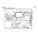
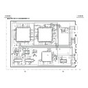
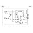
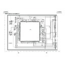
SCHEMATIC DIAGRAM: OUTPUT UNIT ................. 20
»
PARTS LIST .............................................................. 30
Seite
»
LISTE VON VERÄNDERTEN TEILEN ........................ 9
»
ELEKTRISCHE EINSTELLUNG ............................... 11
»
BLOCKSCHALTBILD ................................................ 16
»
GESAMTSCHALTPLAN ........................................... 18
»
SCHEMATISCHER SCHALTPLAN
AUSGABEEINHEIT .................................................. 20
AUSGABEEINHEIT .................................................. 20
»
ERSATZTEILLISTE .................................................. 30
CONTENTS
INHALT
Die LCD-Bildschirme dieser Modelle wurden gemäß den vorhandenen Modellen XG-C40XU/XE
neu konstruiert. Diese Service-Anleitung beinhaltet die Veränderungen, welche sich von den
Grundmodellen unterscheiden.
Beziehen Sie sich für die unveränderten Service-Informationen der Grundmodelle (XG-C40XU/
XE) auf die Service-Anleitung (S01B4XG-C40XU).
neu konstruiert. Diese Service-Anleitung beinhaltet die Veränderungen, welche sich von den
Grundmodellen unterscheiden.
Beziehen Sie sich für die unveränderten Service-Informationen der Grundmodelle (XG-C40XU/
XE) auf die Service-Anleitung (S01B4XG-C40XU).
BESCHREIBUNG
S22F7XGC40XU1
2
XG-C40XU
(
1
)
XG-C40XE
(
1
)
Ref.No.
Description
Current
New
Note
LCD PANELS
XG-C40XU(1)
/
XG-C40XE(1)
LCD Module Unit Red
RLCDP141CEZZ
RLCDPA004WJZZ
LCD Module Unit Green
RLCDP142CEZZ
RLCDPA005WJZZ
LCD Module Unit Blue
RLCDP143CEZZ
RLCDPA006WJZZ
PWB ASSEMBLIES
XG-C40XU(1)
Signal Unit
DUNTKA211DE11
DUNTKB116DE04
Six parts changed
PC Terminal Unit
DUNTKA212DE11
DUNTKB117DE04
No parts changed
S-Out/Regulater Unit
DUNTKA693FE01
DUNTKA693FE04
No parts changed
Output Unit
DUNTKA694FE01
DUNTKB181FE01
Video Unit
DUNTK9769DE24
AC Inlet Unit
RUNTK0677CEZZ
Power Unit
RDENC0334CEZZ
Ballast Unit
RDENC0333CEZZ
PC I/F Unit
CPCi-0047CE15
CPCi-0047CE18
No parts changed
PWB ASSEMBLIES
XG-C40XE(1)
Signal Unit
DUNTKB116DE02
DUNTKB116DE05
No parts changed
PC Terminal Unit
DUNTKB117DE02
DUNTKB117DE05
No parts changed
S-Out/Regulater Unit
DUNTKA693FE02
DUNTKA693FE05
No parts changed
Output Unit
DUNTKA694FE02
DUNTKB181FE02
Video Unit
DUNTK9769DE25
AC Inlet Unit
DUNTK0677CEZZ
Power Unit
RDENC0334CEZZ
Ballast Unit
RDENC0333CEZZ
PC I/F Unit
CPCi-0047CE16
CPCi-0047CE19
No parts changed
SIGNAL UNIT
XG-C40XU(1)
C886
Capacitor 22 16V EL.
—
VCEAPF1CW226M
C887
Capacitor 10 16V EL.
—
VCEAPF1CW106M
R1010
Resistor 0 1/16W M-Ox.
—
VRS-CY1JF000J
R1011
Resistor 0 1/16W M-Ox.
—
VRS-CY1JF000J
R1013
Resistor 0 1/16W M-Ox.
—
VRS-CY1JF000J
R1814
Resistor 0 1/16W M-Ox.
—
VRS-CY1JF000J
OUTPUT UNIT
XG-C40XU(1)
/
XG-C40XE(1)
Refer to Parts List
CABINET AND MECHANICAL PARTS
XG-C40XU(1)
/
XG-C40XE(1)
3-2
Bottom Cabinet Ass
’
y
DBDYU1140CEK1
DBDYU1140CEK2
XG-C40XU1
3-2
Bottom Cabinet Ass
’
y
DBDYU1141CEK1
DBDYU1141CEK3
XG-C40XE1
LIST OF CHANGED PARTS
3
XG-C40XU
(
1
)
XG-C40XE
(
1
)
Ref.No.
Description
Current
New
Note
OPTICS MECHANISM PARTS
XG-C40XU(1)
/
XG-C40XE(1)
6-37
LCD Module Unit Red
RLCDP0141CEZZ
RLCDPA004WJZZ
6-38
LCD Module Unit Green
RLCDP0142CEZZ
RLCDPA005WJZZ
6-39
LCD Module Unit Blue
RLCDP0143CEZZ
RLCDPA006WJZZ
6-47
Screw M2.6-8, x12
XASSF26P06000
XASSF26P08000
6-83
Emergent Polarizer B
PFiLW0295CEZZ
PFiLW0300CEZZ
6-91
Flyeye Lens Aperture
PSLDP3078CEFW
—
Delete
SUPPLIED ACCESSORIES
XG-C40XU(1)
/
XG-C40XE(1)
CD-ROM
UDSKA0053CEN1
UDSKA0059CEN1
CD-ROM
UDSKA0057CEN1
UDSKA0059CEN1
SERVICE JIGS
XG-C40XU(1) XG-C40XE(1)
Extension Cable 20-pin
QCNW-5058CEZZ
QCNW-5419CEZZ
Extension Cable 32-pin
QCNW-5688CEZZ
QCNW-4852CEZZ
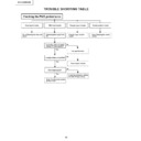
Clearing the Password
ON ENTER ON ENTER ON ENTER
MENU
MENU
If you forget your password, you can use the following
procedure to clear the password.
procedure to clear the password.
This procedure can be performed either from the projector
or with the remote control.
or with the remote control.
(Slide the MOUSE/ADJUSTMENT switch
on the remote control to the ADJ.position.)
on the remote control to the ADJ.position.)
4
XG-C40XU
(
1
)
XG-C40XE
(
1
)
ELECTRICAL ADJUSTMENT
Hook up a signal generator, or a DOSV or Mac personal computer to the projector in order to feed the
signals specified in the Adjusting conditions.
signals specified in the Adjusting conditions.
No.
Adjusting point
Adjusting conditions
Adjusting procedure
1
EEPROM
initialization
initialization
1. Turn on the power (make
sure the lamp lights up) and
warm up the unit for 15 min-
utes.
warm up the unit for 15 min-
utes.
»
Make the following settings:
Press SW5101 to call up the process mode and
execute S2 in the SSS menu. Now the system, with
the PC board not included, is initialized. Do not
execute S1 because otherwise the PC board will
be initialized.
To adjust the PC board, follow the instruction in
"Adjusting the PC board".
Press SW5101 to call up the process mode and
execute S2 in the SSS menu. Now the system, with
the PC board not included, is initialized. Do not
execute S1 because otherwise the PC board will
be initialized.
To adjust the PC board, follow the instruction in
"Adjusting the PC board".
2
3.3V power
supply
adjustment
supply
adjustment
1. Turn on the power.
2. Connect the digital voltme-
2. Connect the digital voltme-
ter to TP1446.
»
Adjust R1649 so that the voltmeter should read
3.43
3.43
±
0.03 Vp-p.
3
2.5V power
supply
adjustment
supply
adjustment
1. Turn on the power.
2. Connect the digital voltme-
2. Connect the digital voltme-
ter to TP1447.
»
Adjust R1652 so that the voltmeter should read
2.60
2.60
±
0.05 Vp-p.
4
R drive
»
Using the control switches or the remote controller
buttons, adjust the data so that the signal be-
comes bit-less (noise).
buttons, adjust the data so that the signal be-
comes bit-less (noise).
1. Feed the 100% red-only sig-
nal. Make the following
choice.
Group : A/D
Subject : R-D
choice.
Group : A/D
Subject : R-D
5
B drive
1. Feed the 100% blue-only
signal. Make the following
choice.
Group : A/D
Subject : B-D
choice.
Group : A/D
Subject : B-D
»
Using the control switches or the remote controller
buttons, adjust the data so that the signal be-
comes bit-less (noise).
buttons, adjust the data so that the signal be-
comes bit-less (noise).
6
G drive
1. Feed the 100% green-only
signal. Make the following
choice.
Group : A/D
Subject : G-D
choice.
Group : A/D
Subject : G-D
»
Using the control switches or the remote controller
buttons, adjust the data so that the signal becomes
bit-less (noise).
buttons, adjust the data so that the signal becomes
bit-less (noise).
3.6Vp-p
(Adjust to 2.5V
DC for red and
blue.)
DC for red and
blue.)
(Adjust to 3.6Vp-p
for green and blue.)
for green and blue.)
2.5V
7
RGB 1 system
black level
signal amplitude
(odd-numbered)
black level
signal amplitude
(odd-numbered)
1. Make the following choice:
Group : OUTPUT 1
Subject : G1-BLK
Subject : G1-BLK
G1-GAIN
For red, choose the sub-
jects R1-BLK and R1-GAIN.
For blue, choose the sub-
jects B1-BLK and B1-GAIN.
jects B1-BLK and B1-GAIN.
2. Connect the oscilloscope to
TP1101 for red.
TP1201 for green.
TP1301 for blue.
TP1301 for blue.
»
Choose the subject G1-GAIN and adjust the sig-
nal amplitude to 3.6
nal amplitude to 3.6
±
0.1 Vp-p using the control
switches or the remote controller buttons.
»
Next,choose the subject G1-BLK and adjust the
white to white level to 2.5
white to white level to 2.5
±
0.1V DC.
»
Adjust the signal's amplitude and white to white
level to 2.5
level to 2.5
±
0.1 DC and 3.6
±
0.1V Vp-p, respec-
tively, for red and blue.

