Sharp XG-C40XE (serv.man18) User Manual / Operation Manual ▷ View online
Operation
18
Operation
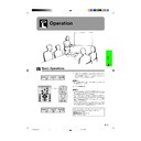
Basic Operations
1 Make the necessary connections before pro-
ceeding. Connect the power cord to a wall outlet.
The POWER indicator illuminates red and the
projector enters standby mode.
The POWER indicator illuminates red and the
projector enters standby mode.
• If the bottom filter cover is not securely installed, the
POWER indicator flashes.
2 Press Power ON.
• The flashing green LAMP REPLACEMENT indicator shows
that the lamp is warming up. Wait until the indicator stops
flashing before operating the projector.
flashing before operating the projector.
• If the power is turned off and then immediately turned on
again, it may take a short while before the lamp turns on.
• If the keylock level is set to “Level A” or “Level B”, Power
ON and Power OFF can only be used on the remote
control. (See page 43.)
control. (See page 43.)
• After the projector is unpacked and turned on for the first
time, a slight odour may be emitted from the exhaust vent.
This odour will soon disappear with use.
This odour will soon disappear with use.
2
When the power is on, the LAMP REPLACEMENT
indicator lights indicating the status of the lamp.
Green: Lamp is ready.
Flashing green: Warming up.
Red: Change the lamp.
indicator lights indicating the status of the lamp.
Green: Lamp is ready.
Flashing green: Warming up.
Red: Change the lamp.
XG-C40XE/CD (E)-c
01.8.1, 5:52 PM
18
Operation
19
Basic Operations
4
3
3 Slide the zoom knob. The image can be adjusted
to the desired size within the zoom range.
4 Slide the focus knob until the image on the screen
becomes clear.
5 Press INPUT to select the desired input mode.
Press INPUT again to change the mode.
EXAMPLE
• When no signal is being received, “NO SIGNAL” will be
displayed. When a signal that the projector is not preset
to receive is being received, “NOT REG.” will be displayed.
to receive is being received, “NOT REG.” will be displayed.
6 Press VOLUME
ⴐ/ⴑ to adjust the volume.
7 Press MUTE to temporarily turn off the sound.
Press MUTE again to turn the sound back on.
8 Press POWER OFF.
Press POWER OFF again while the message is
displayed.
displayed.
• If you accidentally pressed POWER OFF and do not want
to turn off the power, wait until the power off screen
disappears.
disappears.
• When POWER OFF is pressed twice, the POWER indicator
will illuminate red and the cooling fan will run for about 90
seconds. The projector will then enter standby mode.
seconds. The projector will then enter standby mode.
• Wait until the cooling fan stops before disconnecting the
power cord.
• The power can be turned on again by pressing POWER
ON. When the power is turned on, the POWER indicator
and the LAMP REPLACEMENT indicator illuminate green.
and the LAMP REPLACEMENT indicator illuminate green.
• The POWER indicator flashes if the bottom filter cover is
not securely installed.
6
7
8
5
5
INPUT 1 Mode
f
d
g
s
INPUT 4
(S-VIDEO) Mode
(S-VIDEO) Mode
INPUT3
(VIDEO) Mode
(VIDEO) Mode
INPUT 2 Mode
6
7
8
WARNING:
The cooling fan in this projector continues to run for about
90 seconds after the projector is turned off. During normal
operation, when turning the power off always use the
POWER OFF button on the projector or the remote
control. Ensure the cooling fan has stopped before
disconnecting the power cord.
DURING NORMAL OPERATION, NEVER TURN THE
PROJECTOR OFF BY DISCONNECTING THE POWER
CORD. FAILURE TO OBSERVE THIS WILL RESULT IN
PREMATURE LAMP FAILURE.
XG-C40XE/CD (E)-c
01.8.1, 5:52 PM
19
Operation
20
The formula for picture size and projection distance
L
1
= 0.1533x
Ⳮ0.1057
L
2
= 0.118x
Ⳮ0.0048
H= 0.0592x
Ⳮ0.1134
• There is an error of
Ⳳ3% in the formula above.
The formula for picture size and projection distance
L
1
= 0.1647x
Ⳮ0.1020
L
2
= 0.1266x
Ⳮ0.0312
H
=
ⳮ0.0166x ⳮ0.0188
• There is an error of
Ⳳ3% in the formula above.
• Values with a minus (
ⳮ) sign indicate the distance of the lens centre below the bottom of the screen.
Position the projector perpendicular to the screen with all feet flat and level to achieve an optimal image.
Move the projector forward or backward if the edges of the image are distorted.
Move the projector forward or backward if the edges of the image are distorted.
• The projector lens should be centred in the middle of the screen. If the lens centre is not perpendicular to the screen, the image will be
distorted, making viewing difficult.
• Position the screen so that it is not in direct sunlight or room light. Light falling directly onto the screen washes out colours, making viewing
difficult. Close the curtains and dim the lights when setting up the screen in a sunny or bright room.
• A polarizing screen cannot be used with this projector.
Place the projector at the required distance from the screen according
to the desired picture size (see the table below).
to the desired picture size (see the table below).
Setting up the Screen
Standard Setup (Front Projection)
H
L
X
45.5 cm
30.2 cm
30.2 cm
22.8 cm
15.5 cm
15.5 cm
13.0 cm
11.2 cm
11.2 cm
9.4 cm
6.1 cm
6.1 cm
Distance from the lens centre to the
bottom of the image (H)
Maximum (L
1
)
14.0 m
9.3 m
7.0 m
4.7 m
4.7 m
4.0 m
3.4 m
3.4 m
2.8 m
1.9 m
1.9 m
Minimum (L
2
)
10.8 m
7.2 m
5.4 m
3.6 m
3.6 m
3.0 m
2.6 m
2.6 m
2.2 m
1.4 m
1.4 m
Projection distance (L)
Picture size (diag.) (X)
NORMAL Mode
(4:3)
(4:3)
WIDE Mode
(16:9)
(16:9)
ⳮ12.7 cm
ⳮ8.5 cm
ⳮ6.4 cm
ⳮ5.7 cm
ⳮ4.5 cm
ⳮ4.3 cm
ⳮ3.9 cm
ⳮ3.6 cm
ⳮ3.1 cm
ⳮ2.6 cm
ⳮ1.7 cm
ⳮ6.4 cm
ⳮ5.7 cm
ⳮ4.5 cm
ⳮ4.3 cm
ⳮ3.9 cm
ⳮ3.6 cm
ⳮ3.1 cm
ⳮ2.6 cm
ⳮ1.7 cm
Distance from the lens centre to the
bottom of the image (H)
Maximum (L
1
)
15.1 m
10.1 m
10.1 m
7.6 m
6.7 m
6.7 m
5.4 m
5.1 m
5.1 m
4.6 m
4.3 m
4.3 m
3.7 m
3.0 m
3.0 m
2.0 m
Minimum (L
2
)
11.6 m
7.7 m
5.8 m
5.1 m
5.1 m
4.1 m
3.9 m
3.9 m
3.6 m
3.3 m
3.3 m
2.8 m
2.3 m
2.3 m
1.5 m
Projection distance (L)
762 cm (300
⬙)
508 cm (200
⬙)
381 cm (150
⬙)
254 cm (100
⬙)
213 cm (84
⬙)
183 cm (72
⬙)
152 cm (60
⬙)
102 cm (40
⬙)
Picture size (diag.) (X)
762 cm (300
⬙)
508 cm (200
⬙)
381 cm (150
⬙)
338 cm (133
⬙)
269 cm (106
⬙)
254 cm (100
⬙)
234 cm (92
⬙)
213 cm (84
⬙)
183 cm (72
⬙)
152 cm (60
⬙)
102 cm (40
⬙)
x: Picture size (diag.) (inches)
L
L
1
: Maximum projection distance (feet)
L
2
: Minimum projection distance (feet)
H: Distance from the lens centre to the
bottom of the image (H) (inches)
x: Picture size (diag.) (inches)
L
L
1
: Maximum projection distance (feet)
L
2
: Minimum projection distance (feet)
H: Distance from the lens centre to the
bottom of the image (H) (inches)
XG-C40XE/CD (E)-c
01.8.1, 5:52 PM
20
Operation
21
Setting up the Screen
Using the Adjustment Foot
You can adjust the height of the image by raising the
projector with the foot release.
projector with the foot release.
1 Press the foot release and lift the projector to the
desired angle. (Adjustable up to approximately
5° from the standard position.)
5° from the standard position.)
2 Remove your hand from the foot release. Once
the adjustment foot has locked in position, release
the projector.
the projector.
3 If the screen is at an angle, the adjuster can be
used to adjust the angle of the image. (Adjustable
up to approximately 1° from the original position.)
up to approximately 1° from the original position.)
1
3
Foot release
Returning the projector to its original position
While holding the projector, press the foot release and slowly lower the projector to its original position.
• When an adjustment is made, the image may become distorted (keystoned), depending on the relative positions of the projector and the
screen.
CAUTION
• Do not press the foot release when the adjustment foot is extended without firmly holding the projector.
• Do not hold the lens when lifting or lowering the projector.
• When lowering the projector, be careful not to get your fingers caught in the area between the adjustment foot and the
• Do not hold the lens when lifting or lowering the projector.
• When lowering the projector, be careful not to get your fingers caught in the area between the adjustment foot and the
projector.
• Optimal image quality can be achieved when the projector is positioned perpendicular to the screen with all feet flat and level.
Reversed Image Setup
Projection using a mirror
• When the distance between the projector and screen
is not sufficient for normal rear projection, you can
use a mirror to reflect the image onto the screen.
use a mirror to reflect the image onto the screen.
• Place a mirror (normal flat type) in front of the lens.
• Project the normal image onto the mirror.
• The image reflected from the mirror is projected onto
• Project the normal image onto the mirror.
• The image reflected from the mirror is projected onto
the translucent screen.
Rear projection
• Place a translucent screen between the projector and
the audience.
• Use the projector’s menu system to reverse the
projected image. (See page 44 for use of this
function.)
function.)
CAUTION
• When using a mirror, be sure to carefully position both the projector and the mirror so the light does not shine into the eyes of
the audience.
Ceiling-mount Setup
• It is recommended that you use the optional Sharp ceiling-
mount bracket for this installation.
• Before mounting the projector, contact your nearest Sharp
Authorised LCD Projector Dealer or Service Centre to obtain
the recommended ceiling-mount bracket (sold separately).
(AN-C30T ceiling-mount bracket, AN-TK201/202 extension
tube for AN-C30T.)
the recommended ceiling-mount bracket (sold separately).
(AN-C30T ceiling-mount bracket, AN-TK201/202 extension
tube for AN-C30T.)
• When the projector is in the inverted position, use the upper
edge of the screen as the base line.
• Use the projector’s menu system to select the appropriate
projection mode. (See page 44 for use of this function.)
XG-C40XE/CD (E)-c
01.8.1, 5:52 PM
21

