Sharp PG-M10XE (serv.man4) Service Manual ▷ View online
10
PG-M10SU/SE
PG-M10XU/XE
PG-M10XU/XE
Louver
Screw
Screw
Top Cover
S-8
Louver
Screw
Screw
DISASSEMBLY AND REASSEMBLY
1. Preparations and precautions
●
Tools required
1. Phillips screwdriver, Nos. 1 and 2
2. Phillips and bladed precision screwdrivers
3. Anti-static wrist band
4. Hexagonal wrench (opposite side: ___ mm)
2. Phillips and bladed precision screwdrivers
3. Anti-static wrist band
4. Hexagonal wrench (opposite side: ___ mm)
●
Precautions for disassembly and reassembly
1. Before starting the procedure, unplug the power cable.
2. Some parts are still hot immediately after operation. Wait until they have cooled down.
3. Restore the components, screws and wires in their original positions.
4. Follow the important notes in handling the components and carrying out the job.
5. Be careful not to confuse the specific component parts for different models.
6. Do not tamper with the unit to ensure safety.
2.Disassembly and reassembly
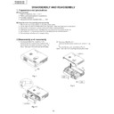
1) Front panel (See Fig. 1 and Fig. 1-A.)
Remove the two screws (S-8) shown in Fig. 1.
Remove the front panel as shown in Fig. 1-A.
Note: Take care not to damage the IR cable.
Remove the front panel as shown in Fig. 1-A.
Note: Take care not to damage the IR cable.
Fig. 1
S-8
Front Panel
1
2
Fig. 1-A
2) Top cover (See Fig. 2.)
Remove the two louver screws (S-8) shown in Fig.
2.
Remove the top cover as shown in Fig. 2.
2.
Remove the top cover as shown in Fig. 2.
Note: Take care not to damage the speaker cable.
Fig. 2
11
PG-M10SU/SE
PG-M10XU/XE
PG-M10XU/XE
3) Speaker, buttons, etc. (See Fig. 3.)
As shown in Fig. 3, remove the nuts, speaker button
OP, and LED lens. Undo the hooks and remove
front buttons.
OP, and LED lens. Undo the hooks and remove
front buttons.
5) Disassembling the front panel (See Fig. 5.)
Remove the screw (S-12) shown in Fig. 5, and
detach the front door.
Remove the screw (S-4) and take out the IR PWB.
Remove the two screws (S-1) and detach the plates.
Remove the screw (S-4) each off the right and left
front hooks, and detach the hooks.
detach the front door.
Remove the screw (S-4) and take out the IR PWB.
Remove the two screws (S-1) and detach the plates.
Remove the screw (S-4) each off the right and left
front hooks, and detach the hooks.
Fig. 5
Front Door
S-4
S-4
S-1
S-12
S-18
S-4
Top Cover
Front Foot
LED
Lens
Lens
Speaker Ass’y
Button
OP
OP
S-25
S-25
Fig. 3
4) Insulation barrier, urethane foam shield, etc. (See
Fig. 4.)
As shown in Fig. 4, the front cabinet is lined with
the barrier sheet.
As shown in Fig. 4, the front cabinet is lined with
the barrier sheet.
Top Cover
Fig. 4
6) F/E PWB (See Fig. 6.)
Remove the screw (S-13) and two screws (S-5)
shown in Fig. 6, and disconnect the connectors.
Remove the screw (S-13) and two RGB spacers,
and detach the connector panel.
shown in Fig. 6, and disconnect the connectors.
Remove the screw (S-13) and two RGB spacers,
and detach the connector panel.
F/E PWB
RGB Spacer
Connector
Panel
Panel
S-23
S-5
S-13
S-5
S-13
S-23
S-23
Fig. 6
12
PG-M10SU/SE
PG-M10XU/XE
PG-M10XU/XE
7) Lamp driver (See Fig. 7.)
Remove the two screws (S-16 and S-17 each)
shown in Fig. 7, and dismount the lamp driver.
shown in Fig. 7, and dismount the lamp driver.
Lamp Driver
S-19
S-16
S-17
Fig. 7
8) Lens base (See Fig. 8.)
Remove the four screws (S-7) shown in Fig. 8, and
detach the lens base.
detach the lens base.
Note: When disassembling or reassembling, be careful
not to get the wires caught. Do not dismount
the spherical mirror and the cylinder mirror out
of the lens base. Otherwise the adjustment will
be lost to produce shadows at the corners of
the screen.
the spherical mirror and the cylinder mirror out
of the lens base. Otherwise the adjustment will
be lost to produce shadows at the corners of
the screen.
Fig. 8
Lens Base
S-7
S-7
S-7
9) Heat sink (See Fig. 9.)
Remove the two screws (S-11) shown in Fig. 9, and
detach the heat sink.
detach the heat sink.
Note: Be careful to fit the heat sink in the correct
direction.
Heat Sink A
Heat Sink B
S-11
Fig. 9
10)DMD and F/M PWB (See Fig. 10.)
Remove the four screws (S-9) shown in Fig. 10,
and detach the DMD and F/M PWB from the lens
base.
and detach the DMD and F/M PWB from the lens
base.
Note: Take care not to touch the elastomer, DMD
surface or terminals, and F/M PWB terminals
by finger. When reassembling, be careful not to
allow dust or dirt on the parts. Special care
should be taken in handling the DMD, elastomer
and F/M PWB, which will directly affect the image
quality.
by finger. When reassembling, be careful not to
allow dust or dirt on the parts. Special care
should be taken in handling the DMD, elastomer
and F/M PWB, which will directly affect the image
quality.
Elastomer
Elastomer
Holder
Holder
DMD
F/M PWB
F/M Angle
S-9
Fig. 10
13
PG-M10SU/SE
PG-M10XU/XE
PG-M10XU/XE
11)Projection lens (See Fig. 11.)
Remove the three screws (S-7) shown in Fig. 11,
and detach the projection lens.
and detach the projection lens.
Note: When reassembling, be careful not to damage
the spherical mirror inside of the lens base.
Projection lens
S-7
S-7
Fig. 11
Fig. 12
12)Color wheel (See Figs. 12 and 13.)
Remove the two screws (S-9) shown in Fig. 12, and
detach the color wheel from the lens base.
Remove the two screws (S-4) shown in Fig. 13, and
detach the wheel cover from the color wheel.
Remove the wheel screw shown in Fig. 13, and
detach the wheel sensor.
detach the color wheel from the lens base.
Remove the two screws (S-4) shown in Fig. 13, and
detach the wheel cover from the color wheel.
Remove the wheel screw shown in Fig. 13, and
detach the wheel sensor.
Note: When reassembling, be careful not to tighten
the screws too much. Otherwise the color wheel
mat come in contact with other components
nearby and fail to rotate. Readjustment will be
needed if the color wheel and the wheel sensor
have been replaced. (Refer to page __.)
mat come in contact with other components
nearby and fail to rotate. Readjustment will be
needed if the color wheel and the wheel sensor
have been replaced. (Refer to page __.)
Color wheel
S-9
S-9
Fig. 13
Wheel Cover
Wheel Sensor
S-4
13)Light tunnel and aperture (See Fig. 14.)
Remove the three screws (S-7) shown in Fig. 14,
and detach the light tunnel from the lens base.
Remove the two screws (S-4) shown in Fig. 14, and
detach the aperture from the lens base.
and detach the light tunnel from the lens base.
Remove the two screws (S-4) shown in Fig. 14, and
detach the aperture from the lens base.
Note: Do not disassemble the light tunnel.
Fig. 14
Light Tunnel
Aperture
S-4
S-7
S-7

