Sharp MX-RB15 (serv.man3) Service Manual ▷ View online
MX-7040N MX-RB15 (CURL CORRECTION UNIT) 16 – 3
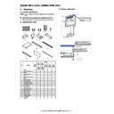
F. Height and tilt adjustment
NOTE: When the adjuster bolt is turned counterclockwise, the
height is decreased. When turned clockwise, the height is
increased.
increased.
NOTE: For the height and tilt adjustment, use the three adjuster
bolts under the unit.
Turn the adjustment nuts of the casters with a wrench in the arrow
direction to adjust the height. (When turning the adjustment nut one
rotation, the height of the curl correction unit is changed by about
1.75mm.)
• To increase the curl correction unit height, turn the nut in the
direction to adjust the height. (When turning the adjustment nut one
rotation, the height of the curl correction unit is changed by about
1.75mm.)
• To increase the curl correction unit height, turn the nut in the
direction [A].
• To decrease the curl correction unit height, turn the nut in the
direction [B].
NOTE: Use the wrench attached to the finisher.
1)
Use adjuster bolt (1) to adjust the height so that the center of
the hole for the unit fixing screw in the F side is aligned with
the center marking-off line.
the hole for the unit fixing screw in the F side is aligned with
the center marking-off line.
2)
Use adjuster bolt (2) to adjust the height so that the center of
the hole for the unit fixing screw in the R side is aligned with
the center marking-off line.
the hole for the unit fixing screw in the R side is aligned with
the center marking-off line.
3)
Use adjuster bolt (3) so that the clearance between the
machine and the unit becomes uniform.
machine and the unit becomes uniform.
G. Fixing to the machine
1)
Fix the unit to the machine with the step screws (Packed
items).
items).
H. Connection of connector to the main unit
1)
Connect the three connectors of the unit to the machine, and
fix with the screws.
fix with the screws.
Ԙ
Ԛ
ԙ
Display

