Sharp MX-PNX1D (serv.man8) Service Manual ▷ View online
MX-FNX1/MX-PNX1 DISASSEMBLY AND ASSEMBLY 6 – 13
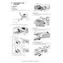
(8) Punch position sensor
1)
Remove the punch unit. Refer to A-(1).
2)
Remove the upper unit. Refer to A-(5).
3)
Remove the harness guide.
4)
Remove the punch position sensor.
(9) Horizontal shift HP sensor
1)
Remove the punch unit. Refer to A-(1).
2)
Remove the guide cover and the harness guide. Refer to A-
(3).
(3).
3)
Disconnect the connector, and remove the harness.
4)
Remove the screws and the pawl, and lift up the harness
guide. Disconnect the connector, and remove the horizontal
shift HP sensor.
guide. Disconnect the connector, and remove the horizontal
shift HP sensor.
(10) Full sensor
1)
Remove the punch unit. Refer to A-(1).
2)
Remove the drive bracket, and remove the full sensor.
3
2
1

