Sharp MX-PNX1C (serv.man8) Service Manual ▷ View online
MX-FNX1/MX-PNX1 DISASSEMBLY AND ASSEMBLY 6 – 4
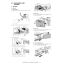
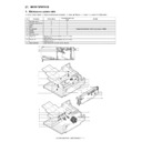
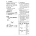
(9) Take-up belt, paper exit roller
1)
Remove the inner finisher from the main unit. Refer to A-(1).
2)
Remove the inner cover. Refer to A-(2).
3)
Remove the reverse guide unit. Refer to A-(5).
4)
Remove the parts, and remove the bundle roller up/down lever
unit.
unit.
5)
Remove the parts, and remove the bundle roller unit.
6)
Remove the parts, and pull out the belt unit. Remove the parts,
and remove the belt unit.
and remove the belt unit.
7)
Remove the parts, and remove the take-up belt and the paper
exit roller.
exit roller.
(10) Inlet port gate
1)
Remove the inner finisher from the main unit. Refer to A-(1).
2)
Remove the inner cover. Refer to A-(2).
3)
Remove the left cover and the bottom cover. Refer to A-(4).
4)
Remove the reverse guide unit. Refer to A-(5).
5)
Remove the PWB. Refer to F-(1).
6)
Remove the flapper solenoid. Refer to B-(2).
7)
Remove the slide rail. Remove the slider fixing bracket and
remove the earth terminal.
remove the earth terminal.
1
1
2
1
1
2
3
1
2
1
2
2
3
1
3
2
1
3
2
MX-FNX1/MX-PNX1 DISASSEMBLY AND ASSEMBLY 6 – 5
8)
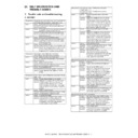
Remove the tray unit.
9)
Remove the harness from the guide, and remove the bottom
plate.
plate.
10) Remove the inlet port upper guide.
11) Remove the spring, and remove the parts. Remove the inlet
port gate.
(11) Inlet port paper transport roller
1)
Remove the inner finisher from the main unit. Refer to A-(1).
2)
Remove the inner cover. Refer to A-(2).
3)
Remove the tray unit. Refer to B-(10).
4)
Remove the bottom plate. Refer to B-(10).
5)
Remove the inlet port upper guide, and remove the transport
guide.
guide.
6)
Remove the parts, and remove the inlet port paper transport
roller.
roller.
(12) Transport motor
1)
Remove the inner finisher from the main unit. Refer to A-(1).
2)
Remove the inner cover. Refer to A-(2).
3)
Remove the tray unit. Refer to B-(10).
4)
Remove the bottom plate. Refer to B-(10).
5)
Disconnect the connector, and remove the transport motor.
1
2
3
1
1
2
3
4
2
1
2
3
MX-FNX1/MX-PNX1 DISASSEMBLY AND ASSEMBLY 6 – 6
(13) Bundle exit motor
1)
Remove the inner finisher from the main unit. Refer to A-(1).
2)
Remove the inner cover. Refer to A-(2).
3)
Remove the tray unit. Refer to B-(10).
4)
Remove the bottom plate. Refer to B-(10).
5)
Disconnect the connector, and remove the bundle exit motor.
(14) Paddle one-rotation solenoid
1)
Remove the inner finisher from the main unit. Refer to A-(1).
2)
Remove the inner cover. Refer to A-(2).
3)
Remove the tray unit. Refer to B-(10).
4)
Remove the bottom plate. Refer to B-(10).
5)
Remove the paddle one-rotation solenoid.
C. Process tray section
(1) Alignment motors F and R
1)
Remove the inner finisher from the main unit. Refer to A-(1).
2)
Remove the inner cover. Refer to A-(2).
3)
Remove the tray unit. Refer to B-(10).
4)
Remove the load cover. Refer to B-(10).
5)
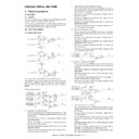
Remove the bundle exit paper transport unit.
6)
Remove each parts, and remove the sensor lever.
7)
Remove the center weight, and remove the process tray unit.
1
2
3
1
1
1
2
1
2
MX-FNX1/MX-PNX1 DISASSEMBLY AND ASSEMBLY 6 – 7
8)
Remove the alignment plate. Remove the screws and the
pawl, and remove the process tray.
pawl, and remove the process tray.
9)
Slide the unit and remove the alignment motors F and R.
(2) Empty sensor, alignment plate HP sensors F and R
1)
Remove the inner finisher from the main unit. Refer to A-(1).
2)
Remove the inner cover. Refer to A-(2).
3)
Remove the tray unit. Refer to B-(10).
4)
Remove the process tray unit. Refer to C-(1).
5)
Remove the bracket and the empty sensor. Remove the align-
ment plate HP sensors F and R.
ment plate HP sensors F and R.
D. Staple section
(1) Staple cartridge
1)
Open the front cover, and slide the inner finisher. Refer to B-
(1).
(1).
2)
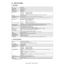
Release the lock, and remove the staple cartridge.
(2) Staple unit
1)
Remove the inner finisher from the main unit. Refer to A-(1).
2)
Remove the inner cover. Refer to A-(2).
3)
Remove the latch cover. Remove the parts and the shaft.
4)
Remove the screw from the bottom. Remove the staple unit,
and disconnect the connector.
and disconnect the connector.
1
2
1
2
4
3
5
1
2

