Sharp MX-M950 / MX-MM1100 (serv.man24) Service Manual ▷ View online
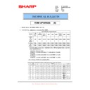
MX-M1100 TRANSFER SECTION L – 1
MX-M1100
Service Manual
[L] TRANSFER SECTION
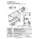
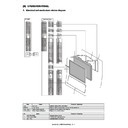
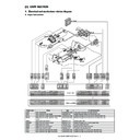
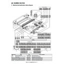
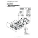
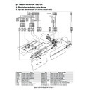
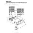
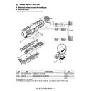
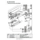
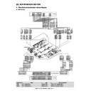
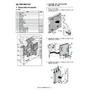
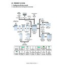
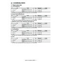
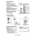
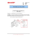
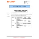
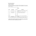
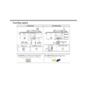
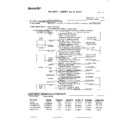
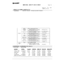
1. Electrical and mechanism relation diagram
In this section, a positive high voltage is applied to paper to transfer toner images from the OPC drum to paper.
No.
Name
Function / Operation
1
Transfer drive roller
Drives the transfer belt.
2
Transfer belt
Transfers toner images from the OPC drum to paper.
3
Transfer roller
Applies a voltage for transfer of toner from the OPC drum to paper.
4
Transfer idle roller
Applies a pressure required for cleaning the transfer belt to the cleaning blade.
5
Transfer tension roller
Applies a proper tension to the transfer belt.
6
Transfer cleaning brush
Scrapes away residual toner from the transfer belt after transfer for cleaning.
7
Transfer cleaning blade
Scrapes away residual toner from the transfer belt after transfer for cleaning.
8
Waste toner transport screw
(Transfer section)
(Transfer section)
Transports waste toner from the transfer unit to the waste toner collection section.
9
Main high voltage PWB
Outputs the transfer voltage and the transfer cleaning voltage.
10
Sub high voltage PWB
Outputs the transfer cleaning voltage.
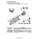
Code
Name
Function / Operation
Type
PTDL
Pre-transfer discharge lamp Reduces the OPC drum potential before transfer to improve the transfer efficiency.
LED
TURS
Transfer solenoid
Separates/attaches the transfer belt from/to the OPC drum.
Solenoid
DM
OPC drum motor
Drives the transfer section.
DC brushless motor
TLS2
Waste toner jam sensor
Detects a waste toner transport jam.
Transmission type photo
sensor
sensor
DM
DM
1
1
TURS
TURS
1
1 2
2
5
5
6
6
7
7
8
8
3
3
4
4
2
2
5
5
6
6
7
7
8
8
3
3
4
4
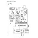
13
GND2
15
+5V_C
17
XDM
19
DMCLK
21
DM-T
3
GND1
8
+38V0
HL PWB
38V0
1
GND1
2
GND2
1
+5V_C
2
XDM
3
DMCLK 4
DM-T
DM-T
5
5 GND1
5
6 +38V0
6
DSW-F-HV
B16B-PASK
CN1
1
13
DF1B-28DES-2.5RC
DF1B-28DEP-2.5RC
DSW-F-HV
13
GND2
2
14 GND2
14
GND2
3
15 GND2
15
XTHV+PWM
7
19 XTHV+PWM 19
XTHV+REM
8
20 XTHV+REM 20
HVREMout
15
27 HVREMout
27
+24V_A
16
28 +24V_A
28
2
B40B-PNDZS-1
CN-3
DSW-F-HV2
4 GND2
6 GND2
9 DSW-F-HV
11 GND2
13 GND2
13 GND2
DSW-F-HV2
B11B-PASK
CN1
1
GND2
2
16 XTHVCLPWM
GND2
3
18 XTHVCLREM
21 XTHV+PWM
XTHVCLPWM
8
22 XBHVREM
XTHVCLREM
9
23 XTHV+REM
XBHVREM
11
1
B2P-VH
THVCL
2 THVCL
37 HVREMout
39 +24V_A
39 +24V_A
THV
PCU PWB
High voltage
PWB unit
PWB unit
(Main)
High voltage
PWB unit
PWB unit
(Sub)
3
2
1
TURS2
3
TURS1
2
+24V_TURS
1
3
2
1
TURS2
3
TURS1
2
+24V_TURS
1
+24V_TURS1
17
+24V_TURS2
16
3
4
4
TURS1
4
TURS2
3
SMR-03V-N/SMP-03V-NC
SMP-06V-NC/SMR-06V-N
DF11-4DP-2C+DF11-4DP-SP1
17
18
18
TURS2
3
TURS1
1
B40B-PNDZS-1
CN19
+24V_TURS1
5
+24V_TURS2
7
4
2
1
3
+24V_TURS2
2 +24V_TURS1
+24V_TURS
B40B-PNDZS-1
CN-21
B10B-PASK-1(LF)(SN)
CN7
SMR-10V-N/SMP-10V-NC
MX-M1100 TRANSFER SECTION L – 2
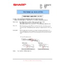
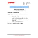
2. Operational descriptions
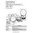
A. Pre-transfer discharge operation
Light is radiated onto the OPC drum after development to reduce
negative charges on the OPC drum. In the areas where toner is
attached to, an electric attraction force between the OPC drum and
toner is weakened to improve the efficiency in transfer operations.
In the areas where toner is not attached to, an electric attraction
force between paper and the OPC drum after transfer is weakened
to improve the separation performance.
B. Transfer operation
A positive high voltage is applied to the transfer roller to charge
paper on the transfer belt positively, transferring negatively
charged toner images onto paper.
paper on the transfer belt positively, transferring negatively
charged toner images onto paper.
(Transfer current)
The transfer current control signal (XTHV+PWM) duty is changed
to control the output current.
The transfer current ON / OFF is controlled by the signal (XTHV +
REM).
In addition, the other transfer current control signal XTHV-PWM
and the transfer current ON/OFF control signal (XTHV-REM) are
outputted simultaneously.
to control the output current.
The transfer current ON / OFF is controlled by the signal (XTHV +
REM).
In addition, the other transfer current control signal XTHV-PWM
and the transfer current ON/OFF control signal (XTHV-REM) are
outputted simultaneously.
C. Transfer belt cleaning operation
In the transfer belt cleaning operation, a negative high voltage
including the AC component is applied to the transfer roller to
attach unnecessary residual toner from the transfer belt to the OPC
drum, cleaning the transfer belt.
including the AC component is applied to the transfer roller to
attach unnecessary residual toner from the transfer belt to the OPC
drum, cleaning the transfer belt.
The transfer belt cleaning control signal (XTHV-PWM) duty is
changed to control the output voltage.
The transfer belt cleaning ON/OFF is controlled by the signal
(XTHV-REM).
On the other hand, the AC component controls the output voltage
by changing the duty of XTHVACPWM. The AC component ON/
OFF is controlled by the signal (XTHVACREM).
The transfer belt cleaning is executed mainly by the transfer blade
belt cleaning belt.
Unnecessary residual toner on the transfer belt is removed and
transported to the waste toner collection section by the waste toner
transport screw.
In addition, the cleaning brush is provided in the transfer section,
where the transfer belt is cleaned, too.
In the transfer belt cleaning, the cleaning roller (brush type)
removes unnecessary residual toner from the transfer belt, and a
positive voltage (+200V) is applied to the removed toner to attach
them to the cleaning roller.
where the transfer belt is cleaned, too.
In the transfer belt cleaning, the cleaning roller (brush type)
removes unnecessary residual toner from the transfer belt, and a
positive voltage (+200V) is applied to the removed toner to attach
them to the cleaning roller.
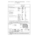
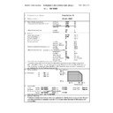
Model
Operation mode
Output current
85 -sheet model
Front print
30uA
Back print
35uA
95 -sheet model
Front print / Back print
40uA
110 -sheet model
Front print / Back print
40uA
PTDL1
PTDL1
OPC drum
CTL
CGL
Aluminum
layer
layer
Cleaning
mode
mode
Transfer
mode
mode
OPC drum
CTL
CGL
Aluminum
layer
-400v/-600v
AC4.5kv
(p-p)
(p-p)
30-40
μA
Cleaning
mode
mode
Transfer
mode
mode
OPC drum
CTL
CGL
Aluminum
layer
-400v/-600v
AC4.5kv
(p-p)
(p-p)
30-40
μA
Cleaning
mode for
transfer belt
mode for
transfer belt
Cleaning
mode for
cleaning roller
mode for
cleaning roller
-500v
+200v
MX-M1100 TRANSFER SECTION L – 3
The toner attached to the cleaning roller is then cleaned by the
cleaning roller cleaning blade.
The transfer cleaning control signal (XTHVCLPWM) duty is
changed to control the polarity and the output voltage.
The transfer cleaning ON/OFF is controlled by the signal (XTHVCL-
REM).
cleaning roller cleaning blade.
The transfer cleaning control signal (XTHVCLPWM) duty is
changed to control the polarity and the output voltage.
The transfer cleaning ON/OFF is controlled by the signal (XTHVCL-
REM).
The cleaning roller itself is also cleaned. In this mode, a negative
voltage (-500V) is applied to attach residual toner on the cleaning
roller to the transfer belt. Then toner attached on the transfer belt is
cleaned by the transfer belt cleaning blade.
The transfer cleaning control signal (XTHVCLPWM) duty is
changed to control the polarity and the output voltage.
The transfer cleaning ON/OFF is controlled by the signal (XTHVCL-
REM).
D. Transfer belt separation operation
The transfer belt separation is executed by the transfer solenoid.
When the print engine receives print data and performs printing,
the transfer belt is in close contact with the OPC drum.
In the following cases, the transfer belt is separated from the OPC
drum.
* When the process control is executed.
* When a jam occurs.
* When the power is turned OFF.
When the print engine receives print data and performs printing,
the transfer belt is in close contact with the OPC drum.
In the following cases, the transfer belt is separated from the OPC
drum.
* When the process control is executed.
* When a jam occurs.
* When the power is turned OFF.
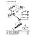
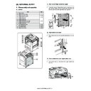
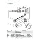
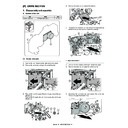
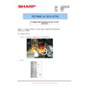
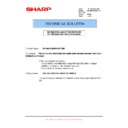
3. Disassembly and assembly
A. Transfer unit
(1) Transfer unit
1)
Open the front cover (a), and pull out the intermediate frame
(b).
(b).
2)
Remove the screw (a), and remove the cover (b).
Cleaning
mode for
transfer belt
mode for
transfer belt
Cleaning
mode for
cleaning roller
mode for
cleaning roller
-500v
+200v
Cleaning
mode for
transfer belt
mode for
transfer belt
Cleaning
mode for
cleaning roller
mode for
cleaning roller
-500v
+200v
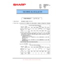
OPC Drum
Unit
Parts
Page
Transfer unit
A
Transfer separation solenoid
L - 4 / a
A
a
b
a
b
MX-M1100 TRANSFER SECTION L – 4
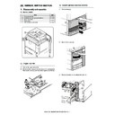
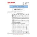
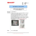
3)
Remove the screw (a), and remove the holder (b).
4)
Remove the transfer belt unit (a).
5)
Disconnect the connector (a), and remove the screw (b).
Remove the trandfer belt frame unit (c).
Remove the trandfer belt frame unit (c).
a. Transfer separation solenoid
1)
Remove the transfer unit.
2)
Remove the screw (a), and remove the transfer cleaning blade
(b).
(b).
3)
Remove the screw (a), and remove the mounting plate (b).
4)
Remove the screw (a), and remove the mounting plate (b).
Remove the stopper (c), the gear (d), the E-ring (e), and the
bearing (f).
Remove the stopper (c), the gear (d), the E-ring (e), and the
bearing (f).
5)
Remove the screw (a), and remove the plate (b). Remove the
bearing (c) and the gear unit (d).
bearing (c) and the gear unit (d).
a
b
a
a
b
b
c
a
b
a
b
a
b
c
d
e
f
a
b
d
c
a
a
Display

