Sharp MX-M950 / MX-MM1100 (serv.man18) Service Manual ▷ View online
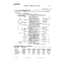
MX-M1100 PAPER TRANSPORT SECTION F – 1
MX-M1100
Service Manual
[F] PAPER TRANSPORT SECTION
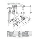
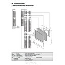
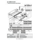
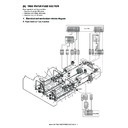
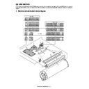
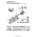
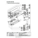
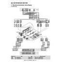
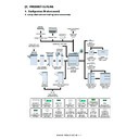
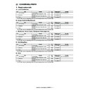
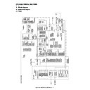
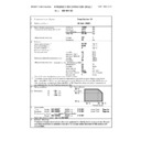
1. Electrical and mechanism relation diagram
A. Paper pass / Vertical transport / LCC interface transport section
Signal name
Name
Type
Function / Operation
C1PFD
Cassette 1 paper entry detection
Reflection type
Detects the cassette 1 paper pass.
C1PPD1
Cassette 1 transport detection 1
Reflection type
Detects the cassette 1 paper transport.
C1PPD2
Cassette 1 transport detection 2
Reflection type
Detects the cassette 1 paper transport.
C1PTC
Horizontal transport clutch
Electromagnetic clutch
Controls ON/OFF of the transport roller.
C2PFD
Cassette 2 paper entry detection
Reflection type
Detects the cassette 2 paper pass.
LCCPTC
LCC transport clutch
Electromagnetic clutch
Controls ON/OFF of the transport roller.
MM1
Paper feed motor 1
DC brushless motor
Drives the paper feed section 1.
PPD1
Transport detection 1
Reflection type
Detects paper transport in the transport path.
VPPD
Vertical transport detection
Reflection type
Detects paper transport in the vertical transport path.
VPTC2
Vertical transport clutch (Intermediate)
Electromagnetic clutch
Controls ON/OFF of the vertical transport roller.
VPTC3
Vertical transport clutch (Upper)
Electromagnetic clutch
Controls ON/OFF of the vertical transport roller.
14
GND2
16
+5V_C
18
XMM
20
MMCLK
22
MM-T
38V0
1
GND1
2
GND2
1
+5V_C
2
XMM
3
MMCLK
4
MM-T
5
3
GND1
3
4
+38V0
4
2
GND1
7
+38V0
HL PWB
PCU PWB
CN-21
B40B-PNDZS-1
1
+24V_A
3
10
+24V_A
2
(NC)
2
3
C1PTC
1
12
C1PTC
BU03P-TR-P-H
+24V_A
28
XLCCPTC
30
3
+24V_A
1
2
(NC)
2
1
XLCCPTC
3
LCCPTC
BU03P-TR-P-H
CN-13
1
+24V_A
3
B36B-PNDZS-1
2
(NC)
2
3
VPTC2
1
2
+24V_A
4
VPTC2
1
+24V_A
3
6
+24V_A
2
(NC)
2
3
VPTC3
1
8
VPTC3
9
+5V_C
11
C2PFD
13
GND2
14
+5V_C
15
+5V_C
16
GND2
17
PPD1
+5V_C
1
4
+5V_C
4
18
C1PFD
C2PFD
2
5
C2PFD
5
19
GND2
GND2
3
6
GND2
6
20
C1PPD1
7
+
5V_C
7
21
+5V_C
+5V_C
1
8
PPD1
8
22
C1PPD2
PPD1
2
9
GND2
9
23
VPPD
GND2
3
10
+5V_C
10
11
VPPD
11
25
GND2
+5V_C
1
12
GND2
12
VPPD
2
GND2
3
+5V_C
1
+5V_C
2
+5V_C
1
+5V_C
3
C1PFD
2
+5V_C
4
GND2
3
1
+5V_C
1
1
+
5V_C
1
2
C1PFD
2
2
C
1PFD
2
3
GND2
3
3G
N
D
2
3
+5V_C
1
4
+5V_C
4
4
+5V_C
4
C1PPD1
2
5
C1PPD1
5
5C
1
P
P
D
1
5
GND2
3
6
GND2
6
6
GND2
6
7
+5V_C
7
7
+5V_C
7
8
C1PPD2
8
8
C
1PPD2
8
9
GND2
9
9
GND2
9
+5V_C
1
C1PPD2
2
GND2
3
GND2
4
GND2
3
GND2
2
GND2
1
DF11-4DS-2C
+
SP1
SMR-12V-N/SMP-12V-NC
BU03P-TR-P-H
BU03P-TR-P-H
DF11-4DS-2C
+
SP1
SMR-09V-B/SMP-09V-BC
SMP-09V-NC/SMR-09V-N
179228-3
179228-3
179228-3
CN6
B14B-PASK-1(LF)(SN)
MM1
MM1
C1PTC
C1PTC
VPTC3
VPTC3
LCCPTC
LCCPTC
VPTC2
VPTC2
VPPD
VPPD
C2PFD
C2PFD
C1PFD
C1PFD
PPD1
PPD1
C1PPD2
C1PPD2
C1PPD1
C1PPD1
SMR-10V-N/SMP-10V-NC
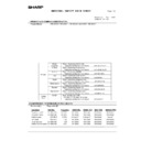
MX-M1100 PAPER TRANSPORT SECTION F – 2
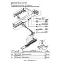
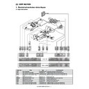
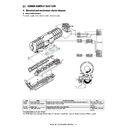
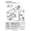
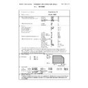
B. Upper transport / PS roller section
Signal name
Name
Type
Function/Operation
APFD1
ADU paper entry detection 1
Reflection type
Detects the ADU paper pass.
APFD2
ADU paper entry detection 2
Reflection type
Detects the ADU paper pass.
CFM-PS
PS cooling fan
Axial-flow fan (40)
Cools the PS section.
DPFS-R
Double feed sensor (receiving)
Supersonic sensor
Detects paper double feed.
DPFS-T
Double feed sensor (transmitting)
Supersonic sensor
Detects paper double feed.
PPD2
Transport detection 2
Reflection type
Detects paper transport in the transport path.
PPD3
Transport detection 3
Reflection type
Detects paper transport in the transport path.
PPD4
Transport detection 4
Reflection type
Detects paper transport in the transport path.
PSM
PS motor
Stepping motor
Drive the PS roller.
TRM
Transport motor
Stepping motor
Drives the transport roller.
VPM
Vertical transport motor
Stepping motor
Drives the vertical transport roller.
PPD4
PPD4
PSM
PSM
TRM
TRM
VPM
VPM
PPD3
PPD3
CFM-PS
CFM-PS
CIS
CIS
PPD2
PPD2
APFD1
APFD1
APFD2
APFD2
DPFS-T
DPFS-T
DPFS-R
DPFS-R
PS/Transfer drawer
CN4
CN1
Double
feed
detection
PWB
CN4
PCU
PPD2,3,4
CN1
CN3
PED
cis
PWB
PSF
PCU PWB
3
2
1
GND2
3
PPD4
2
+5V
1
+24V-PS
14
RXD_CIS
12
+24V-PSM1
1
RSE_CIS
11
GND2
13
PSM_A//
18
+24V-PSM2
2
PSM_A/
19
+24V(ON/OFF)
15
5V_PS
10
GND2
9
PPD4
8
PPD3
7
PPD2
6
n_GCS
5
n_GINC
4
DPFCK
3
GND2
2
DPFAout
1
GND2
20
GND2
19
GUn_D
17
GND2
16
GND2
14
5V_C
13
APFD1
11
APFD2
10
FRM_CIS
9
CLK_CIS
8
PAGE_CIS
7
DPF
18
1
2
2
1
2
5
6
7
8
9
10
11
12
13
14
15
16
17
18
19
2
5
6
7
8
9
10
11
12
13
14
15
16
17
18
19
ADD_CIS
6
TXD_CIS
5
PSM_B/
2
PSM_B//
1
1
2
3
4
5
6
7
8
10
11
12
13
14
15
16
19
20
2
3
4
5
6
7
8
10
11
12
13
14
15
16
19
20
+12V_PS
15
+5V_APFD1
1
APFD1
2
GND2
3
+5V_APFD2
1
APFD2
2
GND2
3
SI
4
CIS_CLK
5
+3.3V
3
+24V
7
GLED
6
1 SIG
GND2
2
6
5
4
3
2
1
+24V-PSM2
6
+24V-PSM1
5
PSM_B/
4
PSM_B//
3
PSM_A//
2
PSM_A/
1
4
2
1
3
+24V(ON/OFF)
3
+24V(ON/OFF)
+24V(ON/OFF)
+24V(ON/OFF)
3
1
2
2
+5V_C
+5V_APFD1
+5V_APFD2
+5V_APFD2
4
2
+5V_PS
19
+24V(ON/OFF)
18
PPD3
13
+12V_PS
12
PPD2
11
GND2
10
n_GCS
9
GUn_D
8
n_GINC
7
FRM_CIS
20
DPF
6
DPFCK
5
GND2
3
GND2
2
DPFAout
1
18
17
15
13
12
11
10
9
8
7
6
5
3
2
1
17
15
13
12
11
10
9
8
7
6
5
3
2
1
PPD4
15
PAGE_CIS
24
RXD_CIS
23
RSE_CIS
21
CLK_CIS
22
19
20
21
22
23
GND2
25
24
ADD_CIS
26
26
25
25
GND2
17
28
27
27
TXD_CIS
28
+24V-PS
27
GND2
1
+24V-PS
2
FRM_CIS
3
CLK_CIS
4
PAGE_CIS
5
ADD_CIS
6
TXD_CIS
7
RSE_CIS
8
RXD_CIS
9
CN19
XCFM-PS
9
+24V-PS
11
CLK_CIS
12
PAGE_CIS
10
CN_LEDout19
2
TXD_CIS
6
ADD_CIS
8
GND2
13
FRM_CIS
14
RXD_CIS
15
APFD2
16
RSE_CIS
17
APFD1
18
+5V_PS
19
GND2
21
PPD4
23
+5V_C
24
PPD3
25
PPD2
27
+12V_PS
28
n_GCS
29
GND2
30
n_GINC
31
GUn_D
32
DPFCK
33
DPF
34
GND2
35
GND2
36
GND2
26
GND2
38
DPFAout
37
CN_LEDin19
40
3
1
2
2
GND2
GND2
GND2
GND2
4
GND2
1
2
GND2
2
DPFS-T
1
DPFS-R
1
GND2
2
GND2
1
+5V_PS
2
+5V
3
GND2
4
LOCK1
9
GND2
10
3
1
2
2
+5V
+5V
+5V
+5V
4
+5V
CN3
VPMB//
4
+24V-PS
5
PSM_A//
8
PSM_B/
9
VPMB/
3
+24V-PSM1 11
PSM_A/
7
+24V-PS
6
1
VPMA/
VPMA//
VPMA//
2
+24V-PSM2 12
PSM_B//
10
1
(95/110only)
(95/110only)
(95/110only)
(95/110only)
2
3
+24V(ON/OFF) 1
LOCK1
2
GND2
3
PSM_A//
1
+24V-PSM1
2
PSM_A/
3
PSM_B//
4
+24V-PSM2
5
PSM_B/
6
6
5
4
3
2
1
GND2
6
APFD2
5
+5V_APFD2
4
GND2
3
APFD1
2
+5V_APFD1
1
+5V
1
PPD2
2
GND2
3
+5V
1
PPD3
2
GND2
3
B08B-PNDZS-1
GND2
1
SIG
2
+3.3V
3
SI
4
CIS_CLK 5
GLED
GLED
6
+24V
7
DPFS-T
1
GND2
2
2
1
GND2
2
DPFS-T
1
CN3
n_GINC
4
GUn_D
5
DPF
3
1
DPFCK
GND2
GND2
2
n_GCS
6
6
5
4
3
2
1
PPD4
6
PPD3
5
PPD2
4
GND2
3
(NC)
2
+5V
1
+5V
1
PPD4
2
GND2
3
1
2
GND2
2
DPFS-R
1
3
1
GND2
GND2
GND2
GND2
GND2
4
2
CN2
DPFAout
2
GND2
3
+12V_PS
4
1
GND2
CN3
7 +24V4A
8 GND1
8 GND1
CN1
GND2
1
1 GND2
1
CN6
+5V_D
2
2 +5V_D
2
+24V4_A
3
3 +24V4_A
3
GND1
4
4 GND1
4
3 5V_D
4 GND2
4 GND2
DCPS2 PWB
(MAIN)
(MAIN)
CN-7
CN-2
XVPMA
3
3
XVPMA
XVPMB
4
4
XVPMB
XVPMXA
5
5
XVPMXA
XVPMXB
6
6
XVPMXB
1 TRMA//
1
CN-4
2 +24V-TR
2
3 TRMB//
3
TRMA/
1
4 TRMA/
4
TRMA//
2
5 +24V-TR
5
TRMB//
3
6 TRMB/
6
TRMB/
4
XTRMA
13
13
XTRMA
+24V-TR
5
XTRMB
14
14
XTRMB
+24V-TR
6
XTRMXA
15
15
XTRMXA
XTRMXB
16
16
XTRMXB
PCU
PWB
PWB
Driver
PWB
(Paper
feed)
1 VPMA/
1
2 VPMA//
2
3 VPMB//
3
4 VPMB/
4
5 +24V-VP 5
6 +24V-VP 6
6 +24V-VP 6
1 VPMA//
2 +24V-VP
3 VPMA/
4 VPMB//
5 +24V-VP
6 VPMB/
2 +24V-VP
3 VPMA/
4 VPMB//
5 +24V-VP
6 VPMB/
MX-M1100 PAPER TRANSPORT SECTION F – 3
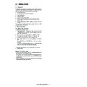
2. Operational descriptions
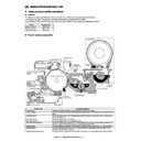
A. Outline
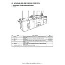
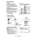
The paper transport section serves the function of transferring
paper from each paper feed port to the registration roller section.
Paper from paper feed tray units 1 and 2, paper feed tray 3 and
paper feed tray 4 is transported vertically to the registration roller
section.
The detection of double-feed is done before transferring paper to
the registration roller, and the check of the off-center is carried out
by the image position sensor.
After the leading edge of the paper is synchronized with the leading
edge of the drum image in the registration roller section, the paper
that is transfer printed with the image in the transfer section passes
through the fusing section and is discharged either face-down or
face-up.
[Operation of Image position sensor]
It detects the position of the paper transferred by the contact image
sensor (CIS) and automatically adjusts the off center.
• CIS: Contact Image Sensor
It detects the position of the paper transferred by the contact image
sensor (CIS) and automatically adjusts the off center.
• CIS: Contact Image Sensor
It is a contact image sensor integrated with the light source, the
lens (Selfoc ) and the sensor.
lens (Selfoc ) and the sensor.
B. Paper transport operation
Straight-Through Path (No Inversion, No Duplexing)
The paper transported from the each tray section is sent to the
paper exit roller (which is driven by the paper exit motor (POM))
with the transport roller).
paper exit roller (which is driven by the paper exit motor (POM))
with the transport roller).
Paper transportation speed
C. Paper face-down output operation
Invertion Path (Face-down Output, No Duplexing)
When face-down print is selected, the paper is passed under the
Face-up/face-down select gate.
After paper passing, the paper exit gate guide falls down by its own
weight.
When the specified time has passed from detection of the paper
lead edge by Face down reverse detection, Paper exit reverse
motor (SBRM) rotates reverse direction in the specified time. (The
rotation time differs depending on the paper size.)
D. Double-feed sensor operation
(1) Outline of the operation
The double-feed sensor is incorporated in the paper transport sec-
tion of 110/95 ppm machine, and it detects double feed.
Paper transport stops when double feed is detected.
tion of 110/95 ppm machine, and it detects double feed.
Paper transport stops when double feed is detected.
Ultrasonic generator generates ultrasound during paper transport.
The level of reception of the ultrasonic sensor largely changes
(decreases) when double feed occurs. Double sheet feed is
detected in this method.
The level of reception of the ultrasonic sensor largely changes
(decreases) when double feed occurs. Double sheet feed is
detected in this method.
Image position sensor
Double feed
detection
1
1
2
Face-up/face-down select gate
Unit (mm/s)
110 / 95CPM
85 CPM
: Normal speed
540
400
(Process speed)
: High speed
600
500
(Paper feed and exit speed)
: High speed
1000
1000
(Switchback speed)
1
2
3
1
3
3
2
2
Face down reverse detection
Face-up/face-down select gate
solenoid OFF-Up, ON-Down
solenoid OFF-Up, ON-Down
ADU gate solenoid
OFF-Left, ON-Right
OFF-Left, ON-Right
Paper
(1 sheet)
(Double feed)
Ultrasound
Ultrasonic
generator
generator
Secondary
radiation
Reflect
Ultrasonic
sensor
sensor
MX-M1100 PAPER TRANSPORT SECTION F – 4
Block diagram
(2) Mechanism and operation of double-feed detection
The sensor is composed of ultrasonic generator part and ultrasonic
detector part. Double feed is detected using 220kHz ultrasound.
Operation when sheets of paper are normally fed one by one
Some of the ultrasound is reflected by the paper, but the ultrasound
reaches the sensor more than the specified level.
The sensor analog output level at that time is 300mV or more, and
digital output level is "L."
Operation when double feed occurs
Most of ultrasound is reflected when double feed occurs, because
the stiffness of paper is high. As a result, the ultrasound which
reaches the sensor is weak, and less than the specified level.
At that time, the sensor analog output level is 300mV or less, the
digital output level is "H."
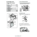
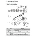
3. Disassembly and assembly
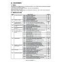
A. Paper pass unit
(1) Paper pass unit
1)
Pull out the tray 1, 2 (a).
2)
Remove the screw (a), and remove the tray 1, 2 (b).
3)
Open the front cover (a), and pull out the intermediate frame
(b).
(b).
4)
Disconnect the connector (a), and remove the screw (b).
Remove the paper pass unit (c).
Remove the paper pass unit (c).
Unit
Parts
Page
Paper pass unit
A
Cassette 1 paper entry detection
F - 5/a
B
Cassette 1 transport detection 1
C
Cassette 1 transport detection 2
Ultrasonic sensor
(DFS PWB)
Ultrasound
generate
generate
Digital signal
output
output
PCU
PWB
Ultrasonic
generator
Amplifier
Detection
circuit
circuit
C
B
A
a
a
a
b
a
a
b
b
b
c
a

