Sharp MX-M850 (serv.man24) Service Manual ▷ View online
MX-M1100 FUSING SECTION N – 4
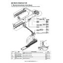
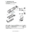
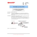
H. Fusing separation pawl operation
The separation pawl of the upper heat roller is of the oscillation type
(oscillation width 3mm), and its operation is synchronized with the
web sheet feed.
To clean the upper heat roller separation pawl, slow rising is per-
formed when rotating the heat roller, and dirt on the pawl is
attached to the upper heat roller and cleaned with the web sheet.
The separation pawl of the lower heat roller is of the separation
type.
The separation pawl of the lower heat roller separates and makes
contact when the heat roller is rotating and stopped, cleaning the
separation pawl.
By the separation operation, dirt on the pawl is removed. The dirt of
the pawl attached to the roller is collected through the upper heat
roller and cleaned with the web sheet.
This separation operation is controlled by the FRS (lower pawl sep-
aration solenoid). When starting rotation, separation is executed for
1sec. When stopping, separation is executed for 1.5 sec.
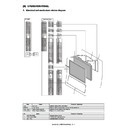
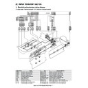
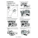
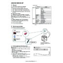
3. Disassembly and assembly
A. Fusing unit
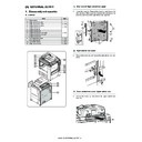
(1) Fusing unit
1)
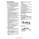
Open the front cover (a), and pull out the intermediate frame
(b).
(b).
2)
While pushing the lever (a), slide the ADU paper exit unit (b).
3)
Remove the screw (a), and remove the cover (b) and the knob
(c).
(c).
4)
Remove the screw (a), and remove the rail (b).
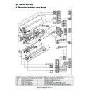
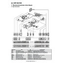
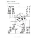
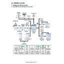
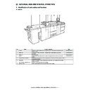
Unit
Parts
Page
Fusing unit
A
Fusing front lower PG home
position detection
position detection
N - 5/a
B
Paper guide motor
C
WEB end detection
N - 5/b
D
WEB near end detection
E
Non-contact thermistor
N - 6/c
F
Thermostat
G
Thermostat
N- 6/d
H
Lower pawl separation solenoid
N - 7/e
G
E
F
D
A
B
C
H
a
b
a
b
a
a
b
c
a
b
MX-M1100 FUSING SECTION N – 5
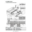
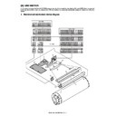
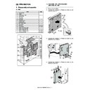
5)
Remove the screw (a), and remove the fusing unit (b).
* Note that the fusing unit is heated to a high temperature,
* Note that the fusing unit is heated to a high temperature,
When removing it, be sure to hold the resin section as indi-
cated below.
cated below.
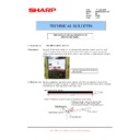
a. Fusing front lower PG home position detection/
Paper guide motor
1)
Remove the fusing unit.
2)
Disconnect the connector (a), and remove the fusing front
lower PG home position detection (b).
lower PG home position detection (b).
3)
Disconnect the connector (a), and remove the screw (b).
Remove the paper guide motor (c).
Remove the paper guide motor (c).
b. WEB end detection / WEB near end detection
1)
Remove the fusing unit.
2)
Remove the screw (a) on the side of "W" mark, and remove
the web unit (b).
the web unit (b).
3)
Remove the screw (a), and remove the cover (b).
4)
Remove the WEB end detection (a) and WEB near end detec-
tion (b). Disconnect the connector (c).
tion (b). Disconnect the connector (c).
a
a
b
a
b
a
b
b
c
a
a
b
W
W
a
a
b
a
b
c
MX-M1100 FUSING SECTION N – 6
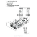
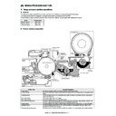
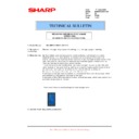
c. Non-contact thermistor / Thermostat
1)
Remove the fusing unit.
2)
Insert a screwdriver into the pressure release shaft (a) to
release the pressure.
* When the pressure is released, the arrow mark on the pres-
release the pressure.
* When the pressure is released, the arrow mark on the pres-
sure release shaft faces obliquely (b). When the pressure is
applied, it faces upward (c).
applied, it faces upward (c).
3)
Remove the screw (a), and separate the fusing upper unit (b)
and the fusing lower unit (c).
* Do not perform pressing operation with the fusing upper unit
and the fusing lower unit (c).
* Do not perform pressing operation with the fusing upper unit
and the fusing lower unit separated from each other.
4)
Remove the screw (a), and remove the cover (b). Disconnect
the connector (c), and remove the screw (d). Remove the Non-
contact thermistor (e).
the connector (c), and remove the screw (d). Remove the Non-
contact thermistor (e).
5)
Remove the screw (a), and remove the terminal (b). Remove
the screw (c) and the washer (d). Remove the thermostat (e).
* When tightening the screw (a), use a great care to tighten it
the screw (c) and the washer (d). Remove the thermostat (e).
* When tightening the screw (a), use a great care to tighten it
securely.
* When the screw becomes loose, replace the screw (a) and
the thermostat (e).
d. Thermostat
1)
Remove the fusing unit.
2)
Insert a screwdriver into the pressure release shaft (a) to
release the pressure.
* When the pressure is released, the arrow mark on the pres-
release the pressure.
* When the pressure is released, the arrow mark on the pres-
sure release shaft faces obliquely (b). When the pressure is
applied, it faces upward (c).
applied, it faces upward (c).
3)
Remove the screw (a), and separate the fusing upper unit (b)
and the fusing lower unit (c).
* Do not perform pressing operation with the fusing upper unit
and the fusing lower unit (c).
* Do not perform pressing operation with the fusing upper unit
and the fusing lower unit separated from each other.
a
c
b
a
a
b
c
a
b
c
e
d
b
b
a
a
c
d
e
a
c
b
a
a
b
c
MX-M1100 FUSING SECTION N – 7
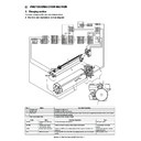
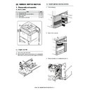
4)
Remove the clip (a), and pull out the shaft (b). Open the paper
gude (c).
gude (c).
5)
Remove the terminal (a). Remove the screw (b) and the
washer (c). Remove the thermostat (d).
* Insert the terminal (a) fully to the bottom until it clicks. Check
washer (c). Remove the thermostat (d).
* Insert the terminal (a) fully to the bottom until it clicks. Check
to confirm that it is securely connected.
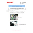
e. Lower pawl separation solenoid
1)
Remove the fusing unit.
2)
Remove the screw (a) and the cover (b). Remove the harness
from the edge saddle (c). Remove the snap band (d) and dis-
connect the connector (e).
Remove the screw (f), and remove the lower heat roller sepa-
ration pawl unit (g).
from the edge saddle (c). Remove the snap band (d) and dis-
connect the connector (e).
Remove the screw (f), and remove the lower heat roller sepa-
ration pawl unit (g).
3)
Remove the screw (a) and remove the lower pawl separation
solenoid (b).
solenoid (b).
b
c
a
a
a
b
c
d
c
a
a
b
e
d
f
g
c
a
b
Display

