Sharp MX-M850 (serv.man24) Service Manual ▷ View online
MX-M1100 FUSING SECTION N – 2
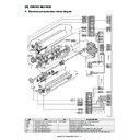
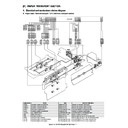
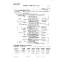
2. Operational descriptions
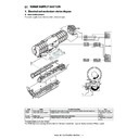
A. Outline
This section performs the following functions and operations.
1)
1)
The fusing roller applies heat and pressure to toner attached to
paper in the transfer section and fuses toner images onto
paper.
• Heat roller diameter:
paper in the transfer section and fuses toner images onto
paper.
• Heat roller diameter:
Upper heat roller 70 mm
Lower heat roller 60 mm
Lower heat roller 60 mm
• Heater lamp:
HL1, HL2, HL4 (Europe 95/110-sheet model only)
2)
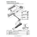
To clean the upper heat roller, the web unit is provided in the
upper section of the upper heat roller.
It is composed of the web sheet feed side, the winding side,
and the back-up roller which is used to press the web sheet
onto the upper heat roller.
In addition, the sensor is provided to detect the remaining
quantity of the web sheet and the end of the websheet.
3)
The thermistor is provided to detect the temperature in the fus-
ing section.
• Upper heat roller center:
ing section.
• Upper heat roller center:
Non-contact type thermistor (Main thermistor)
• Upper heat roller edges:
Contact type thermistor (Sub thermistor)
• Lower heat roller edges:
Contact type thermistor (The thermistor (PRTH) is used only
in the 85-sheet machine for Japan.)
(Though the other fusing units do not employ PRTH, only the
PRTH connector section of the fusing unit of the 85-sheet
machine for Europe is processed with short pins for identifi-
cation of the unit model.)
(In the other fusing units, the PRTH connector section is
open.)
4)
The thermostats are provided for safety of the fusing section.
• HLTS1: Thermostat (1) Cuts conduction to HL1 and HL4.
• HLTS2: Thermostat (2) Cuts conduction to HL2.
• HLTS1: Thermostat (1) Cuts conduction to HL1 and HL4.
• HLTS2: Thermostat (2) Cuts conduction to HL2.
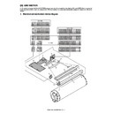
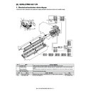
B. Fusing roller drive
To drive the fusing roller, the drive power is transmitted from the
drive motor (FUM) through the connection gear to the upper heat
roller gear.
The drive motor (stepping motor) is driven according to the control
signal sent from the PCU.
drive motor (FUM) through the connection gear to the upper heat
roller gear.
The drive motor (stepping motor) is driven according to the control
signal sent from the PCU.
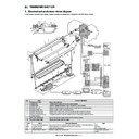
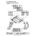
C. Heater lamp drive
The surface temperature of the heat roller detected by the ther-
mistor is sent to the PCU. When it is lower than the specified level,
the PCU sends the heater lamp lighting signal to the heater lamp
drive circuit in the HL PWB.
When the power triac is turned ON through the photo triac coupler
in the heater lamp drive circuit, the AC power is supplied to the
heater lamp to turn it on and heat the heat roller.
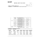
HLTS1
Thermostat (1)
Cuts conduction to the heater lamp when the temperature rises abnormally.
(HL1, HL4)
(HL1, HL4)
HLTS2
Thermostat (2)
Cuts conduction to the heater lamp when the temperature rises abnormally.
(HL2)
(HL2)
RTH1_com
Upper heat roller thermistor
Thermistor
Detects the temperature of the upper heat roller [Center section]
(Non-contact, detection side)
(Non-contact, detection side)
RTH1_d
Upper heat roller thermistor
Thermistor
Detects the temperature of the upper heat roller [Center section]
(Non-contact, detection side)
(Non-contact, detection side)
RTH2
Upper heat roller thermistor 2
Thermistor
Detects the temperature of the upper heat roller (Both edges)
WEBED
Web end sensor
Thermistor
Detects Web End.
WEBM
Web roller drive motor
Controls the web motor.
WEBSPD
Web remaining quantity sensor
Transmission
Detects the web remaining quantity.
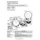
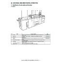
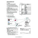
No.
Name
Function /Operation
1
Upper heat roller
Applies heat and pressure to toner on paper to fuse.
2
Upper heat roller separation pawl
Mechanically separates paper which is not separated naturally from the upper heat roller.
3
Lower heat roller
Applies heat and pressure to toner on paper to fuse.
4
Lower heat roller separation pawl
Mechanically separates paper which is not separated naturally from the lower heat roller.
5
Web roller
Cleans the upper heat roller.
6
Web backup roller
Applies a pressure to web paper to bring it into contact with the upper heat roller.
7
Fusing paper guide
Determines the height of paper stack in the fusing section.
(The height can be adjusted with SIM 43-33. Normally it is set to the default value.)
(The height can be adjusted with SIM 43-33. Normally it is set to the default value.)
Code
Name
Type
Function / Operation
Upper heat roller
Upper heater lamp
Fusing paper guide
composed of the
web roller feed side
web roller feed side
composed of the
web roller winding side
web roller winding side
Upper heat roller
separation pawl
separation pawl
Lower heat roller
separation pawl
separation pawl
Web backup roller
Lower heat roller
MX-M1100 FUSING SECTION N – 3
D. Fusing operation
The upper and lower heat rollers apply heat and pressure to toner
on paper, fusing toner images on paper.
on paper, fusing toner images on paper.
A heat roller of silicon rubber is used in this fuser. This is due to the
following:
1)
following:
1)
The upward separation is executed. (Since the hardness of the
upper heat roller is high, the lower heat roller is deformed to
face up paper).
upper heat roller is high, the lower heat roller is deformed to
face up paper).
2)
The nip quantity is increased as it will increase the heating
capacity of the paper. (Nip quantity: 10 - 11mm)
capacity of the paper. (Nip quantity: 10 - 11mm)
3)
A flexible roller allows the toner to fuse without deforming the
toner shape.
toner shape.
E. Fusing temperature control
Thermistors are provided at the center and the edges of the upper
heat roller.
The roller temperature is detected by the installed thermistor, and
the heater lamp is controlled to maintain the temperature at the
specified level.
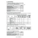
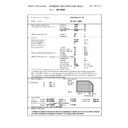
The initial values of the specified temperature are as shown in the
table. (The fusing temperature can be set with Sim. 43-1.)
heat roller.
The roller temperature is detected by the installed thermistor, and
the heater lamp is controlled to maintain the temperature at the
specified level.
The initial values of the specified temperature are as shown in the
table. (The fusing temperature can be set with Sim. 43-1.)
(*1) North America: 160
°C
Europe: 175
°C
F. Fusing temperature control when heavy paper
is fed though the fuser
When heavy paper is fed, the heater lamp is controlled to maintain
the heat roller temperatures at the specified levels below. In addi-
tion, the SM (resist roller control motor) operation start temperature
is set to improve the job efficiency and the fusing performance.
The default values of the specified levels are as shown in the table
below. (The fusing temperature can be set with Sim. 43-1.)
When paper is fed from the tray which is set as a heavy paper tray,
the fusing temperature is changed to that for feeding heavy paper
and CPM falls to about 75%. (The process speed is not changed.)
After completion of paper feed from the heavy paper tray (when the
tray is set to a normal paper tray, or the job is completed and the
machine enters the ready state, etc.), the fusing temperature is set
to the normal setting.
Heavy paper: Heavy paper 1/2/3/4 and tab sheet.
G. Cleaning operation
The heat roller is cleaned by the web unit.
The web diameter is 54mm, and the web sheet length is 50m.
After completion of a job, there is feed of 7mm (Max.) to 2mm. The
difference of 7mm to 2mm depends on the job quantity and the
pixel counter.
Also after completion of warming up, it is fed by 7mm. This is
because the web sheet is pushed against the upper heat roller by
the backup roller and dirt on the web sheet must be removed.
The feed quantity of the web sheet is 0.5mm / 7 copies (variable
with Sim. 43-32).
The web sheet remaining quantity is detected by two sensors
(WEBED, WEBSPD) attached to the web unit.
In case of Web Near End, "Ready to scan for copy. (Maintenance
required.Code: FK3)" is displayed.
In case of Web End, the code FK3 is displayed and the machine is
stopped.
Replace the web unit, and clear the web feed counter with Sim. 24-
4. (The display of FK3 is also deleted.)
When the web unit is not installed, the FK3 code is displayed. In
this case, set the web unit and cancel it with Sim.14. (The FK3
code is deleted, but the web feed counter continues the operation.)
State
95/110-sheet
machine
85-sheet
machine
Upper heat roller
Ready standby
190
°C
180
°C
Preheat standby
(*1)
160
°C
State
95/110-sheet
machine
85-sheet
machine
Upper heat roller
Fusing control
temperature
temperature
205
°C
195
°C
PSM operation start
temperature (RTH1,
center section)
temperature (RTH1,
center section)
193
°C
183
°C
PSM operation start
temperature (RTH2,
edge section)
temperature (RTH2,
edge section)
190
°C
180
°C
composed of the
web roller feed side
web roller feed side
WEBED
WEBSPD
composed of the
web roller winding side
web roller winding side
Upper heat roller
The remaining toner or paper dust etc.
on the upper heat roller.
on the upper heat roller.
Web backup roller
MX-M1100 FUSING SECTION N – 4
H. Fusing separation pawl operation
The separation pawl of the upper heat roller is of the oscillation type
(oscillation width 3mm), and its operation is synchronized with the
web sheet feed.
To clean the upper heat roller separation pawl, slow rising is per-
formed when rotating the heat roller, and dirt on the pawl is
attached to the upper heat roller and cleaned with the web sheet.
The separation pawl of the lower heat roller is of the separation
type.
The separation pawl of the lower heat roller separates and makes
contact when the heat roller is rotating and stopped, cleaning the
separation pawl.
By the separation operation, dirt on the pawl is removed. The dirt of
the pawl attached to the roller is collected through the upper heat
roller and cleaned with the web sheet.
This separation operation is controlled by the FRS (lower pawl sep-
aration solenoid). When starting rotation, separation is executed for
1sec. When stopping, separation is executed for 1.5 sec.
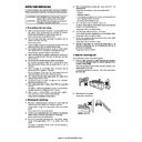
3. Disassembly and assembly
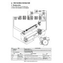
A. Fusing unit
(1) Fusing unit
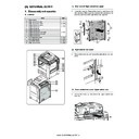
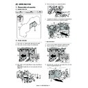
1)
Open the front cover (a), and pull out the intermediate frame
(b).
(b).
2)
While pushing the lever (a), slide the ADU paper exit unit (b).
3)
Remove the screw (a), and remove the cover (b) and the knob
(c).
(c).
4)
Remove the screw (a), and remove the rail (b).
Unit
Parts
Page
Fusing unit
A
Fusing front lower PG home
position detection
position detection
N - 5/a
B
Paper guide motor
C
WEB end detection
N - 5/b
D
WEB near end detection
E
Non-contact thermistor
N - 6/c
F
Thermostat
G
Thermostat
N- 6/d
H
Lower pawl separation solenoid
N - 7/e
G
E
F
D
A
B
C
H
a
b
a
b
a
a
b
c
a
b
MX-M1100 FUSING SECTION N – 5
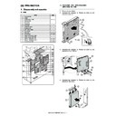
5)
Remove the screw (a), and remove the fusing unit (b).
* Note that the fusing unit is heated to a high temperature,
* Note that the fusing unit is heated to a high temperature,
When removing it, be sure to hold the resin section as indi-
cated below.
cated below.
a. Fusing front lower PG home position detection/
Paper guide motor
1)
Remove the fusing unit.
2)
Disconnect the connector (a), and remove the fusing front
lower PG home position detection (b).
lower PG home position detection (b).
3)
Disconnect the connector (a), and remove the screw (b).
Remove the paper guide motor (c).
Remove the paper guide motor (c).
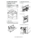
b. WEB end detection / WEB near end detection
1)
Remove the fusing unit.
2)
Remove the screw (a) on the side of "W" mark, and remove
the web unit (b).
the web unit (b).
3)
Remove the screw (a), and remove the cover (b).
4)
Remove the WEB end detection (a) and WEB near end detec-
tion (b). Disconnect the connector (c).
tion (b). Disconnect the connector (c).
a
a
b
a
b
a
b
b
c
a
a
b
W
W
a
a
b
a
b
c
Display

