Sharp MX-M266N / MX-M316N / MX-M356N (serv.man5) Service Manual ▷ View online
Symbols in this manual
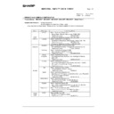
The lists of symbols used in this manual are shown below.
The meaning of each symbol described in the table must be understood for proper servicing.
The meaning of each symbol described in the table must be understood for proper servicing.
1. Symbols used for notes and
cautions
2. Symbols used in the work
contents
Symbol
Meaning
CAUTION
Indicates a general
caution item.
caution item.
HIGH TEMP
Be careful of a high
temperature in the
fusing section.
temperature in the
fusing section.
HIGH VOLTAGE
Be careful of an electric
shock where a high
voltage is applied such
as the high voltage
PWB, the main charger,
and the process section.
shock where a high
voltage is applied such
as the high voltage
PWB, the main charger,
and the process section.
DANGER
Indicates danger.
HANDLE WITH
CARE
CARE
Indicates a part which
requires special care for
handling such as the
HDD, and the LSU.
requires special care for
handling such as the
HDD, and the LSU.
INHIBIT
Indicates inhibit.
NO
ELECTROSTATIC
CHARGE
ELECTROSTATIC
CHARGE
Be careful to keep away
from static electricity.
(PWB's and electric
parts)
from static electricity.
(PWB's and electric
parts)
NO DUST,
FINGER PRINT,
DIRT, SCRATCH
FINGER PRINT,
DIRT, SCRATCH
Be careful not to touch
directly, such as the
optical section, the
photoconductor, and the
DV roller.
Also be careful not to
scratch.
directly, such as the
optical section, the
photoconductor, and the
DV roller.
Also be careful not to
scratch.
NO SCRATCH
NO LIGHT
Be careful not to expose
to light, such as the
photoconductor, and the
test chart.
to light, such as the
photoconductor, and the
test chart.
NO SOLVENT
Be careful not to use a
solvent in cleaning, etc.
solvent in cleaning, etc.
NO DISASSEMLE
Do not disassemble.
Not serviceable.
Example CCD unit.
Not serviceable.
Example CCD unit.
OK/GOOD
Indicates a correct
procedure or result in an
adjustment, etc.
procedure or result in an
adjustment, etc.
NO GOOD
Indicates a wrong
procedure or result in an
adjustment, etc.
procedure or result in an
adjustment, etc.
NOTE
Indicates a note.
IMPORTANT
Indicates an important
item.
item.
REFER
Indicates a reference
page, etc.
page, etc.
NEW
Indicates a new
technology, a new
method, or a new item.
technology, a new
method, or a new item.
EXAMPLE
Indicates a description
using an example.
using an example.
Symbol
Meaning (Work content)
Adhesion
Indicates that a seal, etc.
is attached.
is attached.
Adjustment
Indicates an adjustment.
Measure a
dimension or a
size.
dimension or a
size.
Indicates that a
dimension or a length is
measured.
dimension or a length is
measured.
Apply grease
Indicates that grease is
to be applied.
to be applied.
Apply conductive
grease
grease
Indicates conductive
grease is applied.
grease is applied.
Cleaning
(Dry)
(Dry)
Indicates clean with a
dry cloth.
dry cloth.
Cleaning
(Wet)
(Wet)
Indicates clean with a
cloth dampened with
water.
cloth dampened with
water.
Cleaning
(Alcohol)
(Alcohol)
Indicates clean with
alcohol.
alcohol.
Cleaning
(Blower)
(Blower)
Indicates cleaning is
done with a blower/
brush.
done with a blower/
brush.
Symbol
Meaning
3. Symbols used for kinds of parts
4. Symbols used for additional
descriptions
Cleaning
(Vacuum)
(Vacuum)
Indicates that cleaning is
performed with a
vacuum cleaner.
performed with a
vacuum cleaner.
Cleaning
(Brush)
(Brush)
Indicates that cleaning is
performed with a brush.
performed with a brush.
Oil
Indicates that oil is
applied to lubricate.
applied to lubricate.
Apply powder.
Indicates that setting
power is applied to the
photoconductor drum,
the transfer belt, etc.
power is applied to the
photoconductor drum,
the transfer belt, etc.
Replace
Indicates that a part is
replaced.
replaced.
Check
Indicates that a check
(replacement,
adjustment, cleaning) is
performed.
(replacement,
adjustment, cleaning) is
performed.
Cut
Indicates that cutting is
performed.
performed.
Loosen
Indicates that a screw is
loosened.
loosened.
Connect
Indicates that a
connector is connected.
connector is connected.
Disconnect
Indicates that a
connector is
disconnected.
connector is
disconnected.
Remove a
harness.
harness.
Indicates that a harness
is unsecured.
is unsecured.
Attach a harness.
Indicates that a harness
is secured.
is secured.
Remove a clamp.
Attach a clamp.
Release a hook.
Indicates that a hook is
released.
released.
Fix a hook.
Indicates that a hook is
fixed.
fixed.
Disengage the
pawl.
pawl.
Symbol
Meaning (Work content)
Engage the pawl.
Screw lock
Indicates that a screw is
secured with adhesive.
secured with adhesive.
Unlock
Turn OFF the
power.
power.
Disconnect the
power plug.
power plug.
Symbol
Meaning (Kinds of parts)
Maintenance
part
part
Indicates a part which is
replaced in a maintenance
procedure.
replaced in a maintenance
procedure.
Consumable
part
part
Indicates a consumable
part such as a
photoconductor,
developer, a transfer belt,
etc.
part such as a
photoconductor,
developer, a transfer belt,
etc.
Waste part
Indicates a waste part
which is consumed but
excluded from the above
consumable parts. (A
roller, a seal, etc.)
which is consumed but
excluded from the above
consumable parts. (A
roller, a seal, etc.)
Unit part
Indicates a part which is
designated as a unit.
designated as a unit.
Included part
Indicates a part which is
included in the package
included in the package
Symbol
Meaning
View from the
top
top
Indicates from which
angle the drawing is
viewed.
angle the drawing is
viewed.
View from the
bottom
bottom
View from the
front
front
View from the
back
back
Symbol
Meaning (Work content)
MX-265N Transit, Installation (using) environment, Note - i
MX-265N
Service Manual
Transit, Installation (using) environment, Note
* About a main unit illustration, it may differ from a target model.
1. Installing (use) conditions
Before installing the machine, check that the following installing
(use) conditions are satisfied.
(use) conditions are satisfied.
If the installing (use) conditions are not satisfied, the machine may
not display full performances, resulting in troubles. It may also
cause safety problems. Therefore, be sure to arrange the installing
(use) conditions before setting up the machine.
not display full performances, resulting in troubles. It may also
cause safety problems. Therefore, be sure to arrange the installing
(use) conditions before setting up the machine.
A. Transportation space
For installation of a large size machine, be sure to check that the
door size is wide enough before bringing in.
door size is wide enough before bringing in.
B. Installing space
The following space must be provided around the machine in order
to assure machine performances and proper operations.
to assure machine performances and proper operations.
If any option is installed, provide the additional space for installing
it.
it.
Adequate space must be provide behind the machine for proper
ventilation heat and dust. If not, the machine cannot exhibit func-
tions against heat and dust, causing some troubles.
ventilation heat and dust. If not, the machine cannot exhibit func-
tions against heat and dust, causing some troubles.
C. Power source (Capacity, voltage, frequency,
safety, plug)
If the power specifications are not satisfied, the machine cannot
exhibit full performances and may cause safety trouble.
exhibit full performances and may cause safety trouble.
Strictly observe the following specifications.
(1)
Power capacity
Check that the following power capacity is satisfied. If not, addition-
ally provide a power source.
ally provide a power source.
Current capacity
Japan: 20A or more
EX 100V: 15A or more
EX 200V: 10A or more
NOTE: Check the shape of the power plug of the machine, and
insert it into a power outlet of the acceptable shape.
(2)
Power voltage
Measure the voltage during copying to check that the voltage is in
the range of the specified voltage
the range of the specified voltage
If the voltage is outside the specified range, please have a certified
electrician upgrade the outlet.
electrician upgrade the outlet.
(An electrical work is required.)
Use of a step-up transformer is also available. In this case, the
capacity must be great enough for the max. power consumption of
the machine.
capacity must be great enough for the max. power consumption of
the machine.
(3)
Power frequency, waveform
The frequency must be within the range of the specified frequency
(4)
Safety
Be sure to properly ground the machine.
Grounding (earth connection) must be performed before inserting
the power plug into the power outlet.
the power plug into the power outlet.
When disconnecting the earth connection, be sure to disconnect
the power plug from the power outlet in advance.
the power plug from the power outlet in advance.
(5)
Power plug
Check the shape of the power plug of the machine, and insert it into
a power outlet of the acceptable shape.
Power plug stated in power capacity.
a power outlet of the acceptable shape.
Power plug stated in power capacity.
D. Floor strength and level
This machine is considerably heavy and becomes heavier with an
option installed.
option installed.
The floor must be strong enough to safely support the weight of the
machine as well as any installed options.
machine as well as any installed options.
If the unit is not horizontally installed, the toner density control is not
performed normally, degrading the copy quality.
performed normally, degrading the copy quality.
If not, color shift or image distortion may occur.
To assure proper Image quality, make sure the machine is setting
level.
To assure proper Image quality, make sure the machine is setting
level.
E. Direct rays of the sun, dust, temperature,
humidity, gasses, chemicals, vibration
(1)
Temperature and humidity (Environmental
conditions)
conditions)
This machine is designed to perform properly under the specified
temperature and humidity. If the temperature and humidity exceeds
the specified range, the machine may not operate properly and or
cause equipment failure.
temperature and humidity. If the temperature and humidity exceeds
the specified range, the machine may not operate properly and or
cause equipment failure.
Especially when the humidity is too high, paper absorbs humidity to
cause a paper jam or dirty copy.
cause a paper jam or dirty copy.
Do not install the machine near a heater, a cooler, or a humidifier.
Condensation may form inside the machine causing multiple trou-
bles. Use enough care for ventilation.
bles. Use enough care for ventilation.
Operational environment
Temperature: 10 to 35
Humidity: 20 to 85% RH
Atmospheric pressure: 590 to 1013hPa (altitude: 0 to 2000 m)
(2)
Contaminates
If dust enters the machine, it may cause dirty copy and a paper
jam, resulting in a shortened lifetime.
jam, resulting in a shortened lifetime.
(3)
Direct sunlight
If the machine is installed under the rays of the sun, the exterior of
the machine may be discolored and abnormal copies may be pro-
duced.
the machine may be discolored and abnormal copies may be pro-
duced.
(4)
Gases and chemicals
Do not install the machine at a place where there are gases and
chemicals. Especially be careful to avoid installation near a diazo-
type copier, which produces ammonium gas.
chemicals. Especially be careful to avoid installation near a diazo-
type copier, which produces ammonium gas.
Copy quality may be adversely affected and a trouble may be
caused.
caused.
(5)
Vibration
Avoid installation near a machine which produces vibrations.
If vibrations are applied to the copier machine, copy images may be
deflected and a trouble may be caused.
deflected and a trouble may be caused.
No.
Content
1
Transportation space
2
Installing space
3
Power source (Capacity, fluctuation, safety)
4
Floor strength
5
Direct rays of the sun, dust, temperature, humidity, gases,
chemicals
chemicals
11-13/16"
(30cm)
(30cm)
11-13/16"
(30cm)
(30cm)
17-23/32"
(45cm)
(45cm)
MX-265N Transit, Installation (using) environment, Note - ii
F. Note for handling PWB and electronic parts
When handling the PWB and the electronic parts, be sure to
observe the following precautions in order to prevent against dam-
age by static electricity.
observe the following precautions in order to prevent against dam-
age by static electricity.
• When in transit or storing, put the parts in an anti-static bag or an
anti-static case and do not touch them with bare hands.
• When and after removing the parts from an anti-static bag (case),
use an earth band as shown below:
• Put an earth band to your arm, and connect it to the machine.
• When repairing or replacing an electronic part, perform the
procedure on an anti-static mat.
G. Note for proper drum, developing and fusing
unit handling
When handling the OPC drum and developing units, observe the
following items.
following items.
Drum unit
• To prevent damage to the OPC drum, avoid working on the drum
unit in high intensity light areas.
• When the OPC drum is removed from the machine, cover it with
light blocking material. (When using paper, use about 10 sheets
of paper to cover it.)
of paper to cover it.)
• Be careful not to attach fingerprints, oil, grease, or other foreign
material on the OPC drum surface.
Developing unit
• Be careful not to "leave” fingerprints, oil, grease, or other foreign
material on the developing unit.
Fusing unit
• Be careful not to "leave” fingerprints, oil, grease, or other foreign
material on the fusing roller.
If these items are neglected, a trouble may be generated in the
copy and print image quality.
copy and print image quality.
2. Transit and delivery
A. Implements, facility, and manpower
It is recommendable to use a forklift for bringing in the machine for
safety.
safety.
If no forklift is available, man-power of two persons is required. The
machine is considerably heavy, and requires safety precautions for
delivery and installation.
machine is considerably heavy, and requires safety precautions for
delivery and installation.
Transit of the machine must be made in packed condition to the
installing place.
installing place.
Use care not to exert vibrations or shocks to the machine when in
transit.
transit.
B. Delivery
Remove the packing materials prior to installation in the office envi-
ronment.
ronment.
No.
Content
Method
1
Implements, facility,
and man power
and man power
Use a forklift. (If no forklift is available,
manpower of two persons is required.)
manpower of two persons is required.)
2
Delivery
Transit must be made in packed condition.

