Sharp MX-FNX2 (serv.man7) Service Manual ▷ View online
MX-FNX2/AR-PN1/MX-RBX1 OPERATIONAL DESCRIPTION 5 – 3
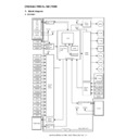
• Inputs to and Outputs from the Finisher Controller PCB (1/2)
• Inputs to and Outputs from the Finisher Controller PCB (2/2)
D. Inputs to and Outputs from the Punch
Controller PCB (option)
• Inputs to and Outputs from the Punch Controller PCB
• Outputs from the Punch Controller PCB
Finisher controller PCB
CN72A-5
Stapler unit
Staple driver home
position sensor
position sensor
Selfprime
sensor
sensor
Staple empty
sensor
sensor
CN11-2
CN11-7
CN11-1
FSTHPD
+5V
+5V
+5V
FSHPD
+5V
HOOK_S
STPL_HP
SLID_HP
STPL_CNCT
Host
machine
CN2-1
-3
-4
-5
-7
-6
-4
-5
-7
-6
CN1-5
CN1-3
CN1-2
CN1-1
+24V
+24V
+5V
+5V
SELF_P
+5V
Staple shift home
position sensor
position sensor
CN11-6
CN11-5
CN11-4
CN11-3
CN72A-4
CN72A-3
CN72A-2
CN72A-6
CN72A-1
CN72A-7
CN72A-5
CN72A-4
CN72A-3
CN72A-2
CN72A-6
CN72A-1
CN72A-7
CN72-5
CN72-4
CN72-3
CN72-2
CN72-6
CN72-1
CN72-7
SLIDMTR_A
SLIDMTR_*A
SLIDMTR_B
SLIDMTR_*B
FSM
CN7-3
CN7-4
CN7-5
CN7-6
CN72B-5
CN72B-4
CN72B-3
CN72B-2
CN72B-5
CN72B-4
CN72B-3
CN72B-2
CN72-10
CN72-11
CN72-12
CN72-13
Staple shift motor
GND
GND
TXD
GND
TXD
RXD
FSPD
FSD
When the stapler is
connected, ‘0’.
connected, ‘0’.
When the cartridge has
staples, ‘0’.
staples, ‘0’.
When the staple is at top
the stapler, ‘0’.
the stapler, ‘0’.
When the stapler is at
stapling home position, ‘0’.
stapling home position, ‘0’.
When the stapler is at home
position, ‘1’.
position, ‘1’.
Communication line
Switches between ‘1’ and
‘0’ according to the direction
ofmotor rotation.
‘0’ according to the direction
ofmotor rotation.
Finisher control PWB
FJPM
Interface
transport
motor
transport
motor
Interface transport
unit inlet port
sensor
unit inlet port
sensor
FJPID
Interface transport
unit outlet port
sensor
unit outlet port
sensor
FJPOD
Interface transport
unit cover sensor
unit cover sensor
FJPDD
CN19-
-2
-3
-4
-5
-3
-4
-5
CNFJ5
CN73B-
-6
-5
-5
-6
-4
-3
-2
-2
*A
*B
A
B
+24V
+24V
CN73D-9
-6
-7
-8
-8
-5
-4
-4
CNFJ1-2
-3
-2
-6
-5
-4
-5
-4
-5
-7
-3
-1
CNFJ1-2
-7
-6
-6
-5
-4
-4
-3
CNFJ2-1
+5V
+5V
+5V
LVL_E_S
LVL_P_S
LVL_C_S
-2
-3
CNFJ3-1
-3
-2
CNFJ4-3
-2
-1
CNFJ1-
CNFJ1-
CNFJ1-
-17
-16
-14
-13
-13
-11
-10
CNFJ1-
CNFJ1-
CNFJ1-
-17
-16
-14
-13
-13
-11
-10
-10
CN73C-1
-2
-3
-3
-5
CN73C-4
CN73C-7
-6
-8
CN73D-2
CN73A-8
CN73A-5
CN73A-2
-7
-6
-4
-3
-3
-1
CN73B-8
CN21-
-2
-3
-3
CN21-4
CN21-7
-5
-6
-8
-9
-9
"0" when paper is detected.
"0" when paper is detected.
"0" when the interface
transport cover is open.
transport cover is open.
The pulse signal is
switched depending
on the motor RPM.
switched depending
on the motor RPM.
Punch controller PCB
-1
J2008-3
+5V
PUNCH
PUNCH
-2
-6
J1006-4
-5
SREG1*
SREG2*
SREG3*
SREG2*
SREG3*
-9
-10
-11
J1007-12
-13
SREG4*
-8
PAEND*
-7
Horizontal
registration
home position
sensor
registration
home position
sensor
FPMCK
-1
J2009-3
+5V
CLOCK
CLOCK
-2
-9
J1006-7
-8
Punch home
position sensor
position sensor
+5V
+5V
PT1
PT2
PT3
PT4
PT5
FPSHPD
FPHPD
-1
J2007-3
+5V
SLIDE
SLIDE
-2
-3
J1006-1
-2
Punch motor
lock sensor
lock sensor
Side resist photo sensor PCB (FPTD)
DUSTLED
Waste full LED PCB
J1005-1
PT131
LED121
DUSTPTR
+5V
4
Waste full photosensor PCB (FPDD)
-2
J1005-3
When the hole puncher is
at home position, ‘0’.
at home position, ‘0’.
While the punch motor
is rotating, alternates
between ‘0’ and ‘1’.
is rotating, alternates
between ‘0’ and ‘1’.
When the punch slide
unit is at home position,
‘1’.
unit is at home position,
‘1’.
When paper is
detected, ‘0’.
detected, ‘0’.
When the light is
blocked, ‘0’.
blocked, ‘0’.
Punch controller PCB
FPSM
Punch side resist motor
B*
A*
B
A
J1001-1
-2
-3
-4
FPNM
Punch motor
J1002-1
-2
LEDON5
LEDON4
LEDON3
LEDON2
LEDON1
LEDON4
LEDON3
LEDON2
LEDON1
-4
-5
-1
J1007-6
+5V
-3
-2
-2
LED5
LED4
LED3
LED2
LED1
Side resist LED PCB (FPSD)
Switches between ‘+’
and ‘–’ according to
the direction ofmotor
rotation.
and ‘–’ according to
the direction ofmotor
rotation.
When ‘1’, LED goes ON.
Switches the pulse
signals according to
the rotation ofthe motor.
signals according to
the rotation ofthe motor.
MX-FNX2/AR-PN1/MX-RBX1 OPERATIONAL DESCRIPTION 5 – 4
2. Feed/Drive System
A. Outline
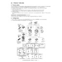
The machine performs the following in response to the commands
coming from its host machine on the sheets arriving from the host
machine for delivery: simple stacking, job offset, and stapling or
folding (in two).
If a punch unit (option) is installed, the sheets are pouched and
delivered to the delivery tray.
Sheets may be delivered in either of five ways (including one for
the punch unit):
(1) Normal Delivery
a. Simple Stacking
The machine pulls in the sheet once to the processing tray and
then delivers it to the delivery tray.
The machine pulls in the sheet once to the processing tray and
then delivers it to the delivery tray.
b. Job Offset
The machine pulls the sheet once to the processing tray. It then
moves the sheet to the front or the rear using the aligning plate.
When it has deposited a specific number of sheets, it delivers them
in the form of a aligning plane. When the number of sheets stacked
on the processing tray reaches a specified value, the sheets are
delivered in a form of a stack.
c. Stapling
The machine stacks sheets coming from its host machine on the
processing tray. When the number of sheets stacked on the pro-
cessing tray reaches a specified value, the finisher staples them
delivers the stapled stack to the delivery tray.
The machine stacks sheets coming from its host machine on the
processing tray. When the number of sheets stacked on the pro-
cessing tray reaches a specified value, the finisher staples them
delivers the stapled stack to the delivery tray.
Punching
Normal delivery
Delivery method
Middle 2-point stapling
Job offset
Simple stacking
Stapling
Front 1-point stapling
Rear 1-point stapling
Middle 2-point stapling
Stitching
Saddle delivery
Tray
Paper
4th set
(direction of delivery)
Results of offset delivery (4 jobs)
2nd set
3rd set
1st set
MX-FNX2/AR-PN1/MX-RBX1 OPERATIONAL DESCRIPTION 5 – 5
d. Saddle Delivery
The machine deposits a stack of sheets on the processing tray, sta-
ples it (middle 2-point), and then moves it to the saddle unit. The
saddle unit folds the stack in two, and delivers it to the bind tray.
The machine deposits a stack of sheets on the processing tray, sta-
ples it (middle 2-point), and then moves it to the saddle unit. The
saddle unit folds the stack in two, and delivers it to the bind tray.
B. Feed/Delivery
(1) Outline
The machine forwards the sheets coming from its host machine to
the delivery tray, processing tray, or saddle unit according to the
type of delivery used. The sheets forwarded to the processing tray
or the saddle unit are offset, stapled, or folded.
The following table shows the motors that are associated with mov-
ing and aligning sheets. These motors are controlled (rotated clock-
wise or counterclockwise) by the microprocessor (CPU) on the
finisher controller PCB.
The paper path is equipped with the sensors shown in the following
figure used to monitor the arrival or passage of sheets.
If a sheet fails to arrive at or move past a specific sensor within a
specific period of time, the finisher controller will assume a jam, and
stops the ongoing operation and, at the same time, communicates
the presence of a jam to the host machine.
Notation
Name
Description
Connector on
finisher
controller PCB
FFM
Feed motor
Stepping motor
CN10
FPM
Paddle motor
Stepping motor
CN10
FAM
Bundle exit motor
Stepping motor
CN13
FFJM
Alignment plate motor
(front)
(front)
Stepping motor
CN3
FRJM
Alignment plate motor
(rear)
(rear)
Stepping motor
CN3
FFSM
Staple motor
Brush DC motor
CN6
FJPM
Interface transport motor
Stepping motor
CN21
Notation
Name
Description
Connector on
finisher
controller PCB
FED
Entry paper sensor
Photointerrupter
CN16
FFPD
Bookbinding position
sensor
sensor
Photointerrupter
CN16
Staple
motor
drive
signal
BINDMTR
Bookbinding
lock
sensor
detect
signal
BIND_CLK
Finisher controller PCB (1/2)
Lift
m
otor
drive
signal
SIFTMTR
Bundle
exit
motor
drive
signal
EJCTMTR
Staple
slide
motor
drive
signal
SLIDMTR
Paddle
motor
drive
signal
PDLMTR
Alignment
motor
(rear)
drive
signal
RJOGMTR
Bind
clutch
dr
iv
e
signal
B_CLU
Interface
transport
m
otor
drive
signal
RIM
Alignment
motor
(front)
drive
signal
FJOGMTR
FFE
FRJM
FPM
FFSM
FFC
FAM
FSM
FLM
FFJM
FJPM
FFM
Finisher controller PCB (2/2)
Feed
motor
drive
signal
F
EEDMTR
Finisher controller PCB
FFPD
Bookbinding
position
detect
signal
BIND_P
FED
Entry
paper
detect
signal
ENT_S
MX-FNX2/AR-PN1/MX-RBX1 OPERATIONAL DESCRIPTION 5 – 6
C. Job Offset
(1) Outline
"Job offset" refers to the operation by which the machine delivers a
set of sheets with them pulled forward or backward for sorting.
Switching between the forward and backward directions is made
using an aligning plate (front) and an aligning plate (rear).
The sheet coming between the delivery rollers is fed onto the pro-
cessing tray and then fed toward the stopper by the paddle.
A swing guide is at the up position while a sheet is being pulled
onto the processing tray or during alignment. It is at the down posi-
tion during stack feeding, stack delivery, or stapling.
At power-on, the finisher controller PCB drives the aligning motor
(front) (FFJM) and the aligning motor (rear) (FRJM) to return the
two aligning plates to their home positions.
(2) Processing Tray Paper Stacking Operation
A sheet coming between the delivery rollers is fed onto the pro-
cessing tray. Then, the paddle taps on the sheet surface to locate
the sheet against the processing tray stopper.
cessing tray. Then, the paddle taps on the sheet surface to locate
the sheet against the processing tray stopper.
(3) Offset Operation
Each sheet is pulled forward or backward using the aligning plate
(front) and the aligning plate (rear).
The offset operation is performed each time a sheet is pulled onto
the processing tray.
Offsetting in the forward direction
(front) and the aligning plate (rear).
The offset operation is performed each time a sheet is pulled onto
the processing tray.
Offsetting in the forward direction
Offsetting in the backward direction
(4) Stack Delivery Operation
Stack delivery takes place when 1 sheet of large-size paper or 25
sheets of small-size paper have been stacked on the processing
tray with them offset in either direction.
The paddle motor (FPM) rotates and the swing guide descends to
hold the paper stack between the upper and lower stack delivery
rollers. The stack delivery motor (FAM) rotates in the forward direc-
tion to rotate the delivery rollers, feeding the paper stack in the
delivery direction. The delivery belt home position sensor is turned
OFF. The delivery motor is driven a specified number of pulses,
causing the swing guide to ascend. Next, the paper delivery motor
is driven. Next, the delivery motor is driven to deliver the paper
stack with the nails of the delivery belt that rotates in sync with the
stack delivery rollers.
Sensor
Symbol
Connector
Aligning home position sensor (front)
FFJHPD
CN4-3
Aligning home position sensor (rear)
FRJHPD
CN5-15
Stack roller home position sensor
FARHPD
CN9-9
Paddle home position sensor
FPDHPD
CN9-3
Function
Motor
Symbol
Drives the aligning plate (front)
Aligning motor (front)
FFJM
Drives the aligning plate (rear)
Aligning motor (rear)
FRJM
Drives the swing guide drive
Paddle motor
FPM
Drives the paddle (feeds paper)
Paddle motor
FPM
Aligning plate
(front)
(front)
Alignment motor (front)
(FFJM)
Aligning home position sensor (front)
(FFJHPD)
Alignment
motor (rear)
motor (rear)
(FRJM)
Light-shielding plate
(Front)
Paper
Light-shielding plate
Aligning home position sensor (rear)
(FRJHPD)
Aligning plate
(rear)
(rear)
Swing guide
Delivery belt
Stack delivery roller (lower)
Processing tray stopper
Paddle
Stack delivery roller (upper)
Aligning plate
Paper
Aligning plate (rear)
Sheet to be offset
Tray
Aligning plate (front)
Tray
Aligning plate (rear)
Sheet to be offset
Aligning plate (front)
Swing guide

