Sharp MX-FN21 / MX-FN22 / MX-PN13 (serv.man6) Service Manual ▷ View online
MX-7040N MX-FN21/FN22 (FINISHER/SADDLE STITCH FINISHER) 20 – 2
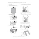
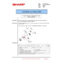
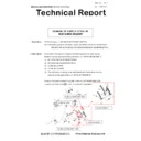
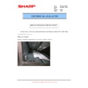
10) Move the finisher from the pallet to the floor slowly.
B. Fixing tape and protection material removal
1)
Remove the fixing tape and the fixing bracket from the finisher.
2)
Remove the screw, and remove the four fixing members of the
lift tray rail section.
lift tray rail section.
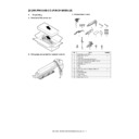
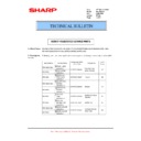
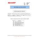
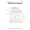
C. Packed items check
MX-FN21
MX-FN22
No.
Name
Quantity
1
Latch receiver
2
2
Positioning pin
1
3
Shunt cable unit
1
4
Wire saddle
1
5
Spacer
1
6
Staple unit staple case
1
7
Spring + small bind screw with flat washer (M4)
1
2
1
4
5
3
7
6
9
8
11
10
13
14
15
12
8
Screw (RS tight, M4 x 8)
9
9
Latch cover
1
10
Screw (Bind, M4 x 6)
2
11
Power cord
1
12
Staple position label (For scanner)
1
13
Staple position label (For DSPF)
1
14
Punch position label (For scanner)
1
15
Punch position label (For DSPF)
1
No.
Name
Quantity
1
Latch receiver
2
2
Positioning pin
1
3
Shunt cable unit
1
4
Wire saddle
1
5
Spacer
1
6
Staple unit staple case
1
7
Power cord
1
8
Screw (RS tight, M4 x 8)
9
9
Earth plate
2
10
Bookbinding tray
1
11
Saddle stitcher unit accessory caster
1
12
Screw (with spring washer)
2
13
Staple position label (For scanner)
1
14
Staple position label (For DSPF)
1
15
Punch position label (For scanner)
1
16
Punch position label (For DSPF)
1
No.
Name
Quantity
2
1
4
5
3
7
6
9
8
10
11
12
14
15
16
13
MX-7040N MX-FN21/FN22 (FINISHER/SADDLE STITCH FINISHER) 20 – 3
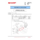
D. Cushion attachment
MX-FN21
MX-FN22
2. Installation
NOTE: Before installation, be sure to turn both the operation and
main power switches off and disconnect the power plug
from the power outlet. Make double sure that the data lamp
on the operation panel does not light up or blink when per-
forming installation.
from the power outlet. Make double sure that the data lamp
on the operation panel does not light up or blink when per-
forming installation.
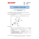
A. Staple unit stale case installation
1)
Open the front cover of the finisher. Insert the staple unit staple
case into the staple unit until it clicks.
case into the staple unit until it clicks.
B. Spacer attachment
1)
Attach the spacer to the inside of [A] at the groove in the right
side of the upper cover of the finisher. Since the groove is
shorter than the spacer, put the spacer in parallel with the top
line where there is no groove.
side of the upper cover of the finisher. Since the groove is
shorter than the spacer, put the spacer in parallel with the top
line where there is no groove.
When the groove is in the front side:
When the groove is in the rear side:
Cushion attachment
position
position
⾍ઃၮḰ
Reference of cushion on.
(Upper cabinet side tier)
(Upper cabinet side tier)
Reference of cushion on.
(Upper cabinet lower edge)
(Upper cabinet lower edge)
Cushion attachment
position
position
Reference of cushion on.
(Upper cabinet side tier)
(Upper cabinet side tier)
Reference of cushion on.
(Upper cabinet lower edge)
(Upper cabinet lower edge)
[A]
[A]
MX-7040N MX-FN21/FN22 (FINISHER/SADDLE STITCH FINISHER) 20 – 4
C. Saddle section installing procedures
(MX-FN22 only)
1)
Open the front cover of the finisher, pull out the hook of the
saddle stitcher unit until it stops.
saddle stitcher unit until it stops.
2)
Attach the saddle stitcher unit accessory caster (Packed items
No.11) with the spring washer screw so that the caster is on
the floor.
(Attach with the two spring washer screws which are included
in the package.)
No.11) with the spring washer screw so that the caster is on
the floor.
(Attach with the two spring washer screws which are included
in the package.)
3)
Connect the connector of the saddle tray to the connector in
the lower left side, and attach the bookbinding tray (Packed
items No.10) with the two hooks.
the lower left side, and attach the bookbinding tray (Packed
items No.10) with the two hooks.
D. Shunt cable unit installation
1)
Fix the shunt cable unit (Packed items No.3) with the screw
(Packed items No.8 RS tight, M4 x 8).
(Packed items No.8 RS tight, M4 x 8).
E. Connection plates F/R, connection pin, paper
guide, and protection Mylar installation
Connection unit: MX-RB15 (Decurler unit)
1)
Fix the latch receivers F/R (Packed items No.1) and the posi-
tioning pin (Packed items No.2) to the decurler unit with the
screws (Packed items No.8 RS tight, M4 x 8). Only for FN-22,
fix the Earth plate (Packed itme No.9) to the latch receivers F/
R.
tioning pin (Packed items No.2) to the decurler unit with the
screws (Packed items No.8 RS tight, M4 x 8). Only for FN-22,
fix the Earth plate (Packed itme No.9) to the latch receivers F/
R.
2)
Fix the paper guide A (bundled with the decurler unit No.11)
and the protection sheet (bundled with the decurler unit No.14)
together with the screws (bundled with the decurler unit No.1).
and the protection sheet (bundled with the decurler unit No.14)
together with the screws (bundled with the decurler unit No.1).
MEMO: Temporarily attach the protection sheet to the decurler
unit with the duplex tape (back of the protection sheet), then fix
it with the screw.
unit with the duplex tape (back of the protection sheet), then fix
it with the screw.
Connection unit: MX-FD10 (Paper folding unit)
1)
Fix the latch receivers F/R (Packed items No.1) and the posi-
tioning pin (Packed items No.2) to the decurler unit with the
screws (Packed items No.8 RS tight, M4 x 8). Only for FN-22,
fix the Earth plate (Packed itme No.9) to the latch receivers F/
R.
tioning pin (Packed items No.2) to the decurler unit with the
screws (Packed items No.8 RS tight, M4 x 8). Only for FN-22,
fix the Earth plate (Packed itme No.9) to the latch receivers F/
R.
)1!
)1!
1
1
1
1
MX-7040N MX-FN21/FN22 (FINISHER/SADDLE STITCH FINISHER) 20 – 5
Connection unit: MX-RB13 (Relay unit)
1)
Fix the latch receivers F/R (Packed items No.1) and the posi-
tioning pin (Packed items No.2) to the relay unit with the
screws (Packed items No.8 RS tight, M4 x 8). Only for FN-22,
fix the Earth plate (Packed itme No.9) to the latch receivers F/
R.
tioning pin (Packed items No.2) to the relay unit with the
screws (Packed items No.8 RS tight, M4 x 8). Only for FN-22,
fix the Earth plate (Packed itme No.9) to the latch receivers F/
R.
2)
Fix the paper guide A (bundled with the decurler unit No.11) to
the relay unit with the screws (bundled with the decurler unit
No.1).
the relay unit with the screws (bundled with the decurler unit
No.1).
F. Finisher connection (common for each unit)
1)
Remove the screw, lift the latch and tighten the screw again to
fix the latch.
fix the latch.
2)
Fit the positioning pin attached to the connection unit with the
positioning hole in the finisher, and connect the finisher with
the connection unit.
positioning hole in the finisher, and connect the finisher with
the connection unit.
3)
Check to confirm that the latch is securely engaged with the
latch holder, and fix the latch with the fixing screw.
latch holder, and fix the latch with the fixing screw.
4)
Attach the latch cover (Packed items No.9) to the latch section
with the screws (Packed items No.10 Bind, M4 x 6) (Only for
FN21)
with the screws (Packed items No.10 Bind, M4 x 6) (Only for
FN21)
G. Shunt cable connection
1)
Connect the shunt cable (Packed items No.3) and the connec-
tion unit with the screw (Packed items No.8).
tion unit with the screw (Packed items No.8).
H. Height and tilt adjustment
MEMO: The specification of the height and the tilt adjustment are
as follows.
as follows.
Height: The difference of level between top surface of the adjacent
device is within
device is within
2mm.
Tilt: The difference of clearance between upper and lower part of
the adjacent device is within
the adjacent device is within
2mm.
1)
Open the front cover, and remove the wrench.
)1!
1
1
1
Display

