Sharp MX-FN19 / MX-FN20 / MX-PN12 (serv.man3) Service Manual ▷ View online
MX-7040N MX-PN12A/B/C/D (PUNCH MODULE) 15 – 4
E. Adjustment
Refer to the adjustment procedure of each finisher.
F. Touch of the auxiliary caster with the floor
Refer to the procedure for touch of the auxiliary caster with the floor
of each finisher.
of each finisher.
G. Install to main unit
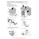
1)
Engage the finisher that has installed punch unit to the main
unit.
unit.
2)
Fix the main unit and the punch unit with the fixing screw
(Package part of MX-FN19, MX-FN20).
(Package part of MX-FN19, MX-FN20).
3)
Install the fixing screw (Package part of MX-FN19, MX-FN20)
on rear side.
on rear side.
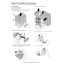
4)
Install the rear cover of punch unit with the fixing screws.
NOTE: Be careful not to damage to the harness at the installa-
tion.
5)
By using nippers, split the removed connector cover of the fin-
isher along the perforated line.
isher along the perforated line.
6)
Install the connector cover of the finisher and fix it with the fix-
ing screw.
ing screw.
MX-7040N MX-PN12A/B/C/D (PUNCH MODULE) 15 – 5
H. Attach the front door
1)
Open the front door of the finisher.
2)
Temporarily fix the screw to the front door of the finisher.
3)
Hook the front door of punch unit to the temporarily fixed
screw.
screw.
4)
Attach the front cabinet with the four screws and tighten the
temporarily fixed screw completely.
temporarily fixed screw completely.
I. Connection of connector to the main unit
1)
Connect two connectors of the finisher to the main unit, and
tighten the screws.
tighten the screws.
J. Punch position label attachment
1)
Attach the punch position label to the position indicated in the
figure.
For scanner (Package part of MX-FN19, MX-FN20)
figure.
For scanner (Package part of MX-FN19, MX-FN20)
MX-7040N MX-PN12A/B/C/D (PUNCH MODULE) 15 – 6
For DSPF (Package part of MX-FN19, MX-FN20)
K. Turn ON the power of the main unit
1)
Connect the power plug of the machine to the power outlet,
and turn ON the main power switch and the operation panel
power switch.
and turn ON the main power switch and the operation panel
power switch.
edge R2.5
Tangential line
of R2.5
Display

