Sharp MX-DEX1 (serv.man10) Service Manual ▷ View online
MX-DEX1/DEX2 ADJUSTMENT 8 – 2
3
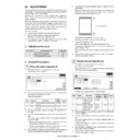
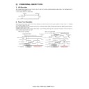
Print leading edge adjustment
1)
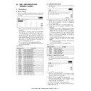
Run SIM50-5 using the keypad on the main unit.
The following screen appears.
The following screen appears.
2)
Press the [EXECUTE] button to highlight it.
The main unit starts printing an adjustment pattern image
using the currently configured values.
Upon completion, the [EXECUTE] button becomes unhigh-
lighted.
* To save the currently configured settings into the EEPROM
The main unit starts printing an adjustment pattern image
using the currently configured values.
Upon completion, the [EXECUTE] button becomes unhigh-
lighted.
* To save the currently configured settings into the EEPROM
and RAM, press any of the following: [
↑] or [↓] button, [OK]
button, [EXECUTE] button, [Color] or [Monochrome] key.
* At any time during printing, you can suspend the test print by
pressing any of the following: the [C] key, [CA] key, [SYS-
TEM SETTING] key, and [EXECUTE] button.
TEM SETTING] key, and [EXECUTE] button.
* After being stopped from printing, the main unit resumes the
self-print test when it becomes ready.
3)
Select "E: PAPER" and choose the desired paper feed location
(in this example, CS3 and CS4).
(in this example, CS3 and CS4).
4)
Check that the adjustment pattern image is printed in the cor-
rect position. Measure the dimensions of the void areas on the
left- and right-frame sides of the adjustment pattern image,
and make sure that the following conditions are met: A=4.0
±2.0 mm B=4.0 ±2.0 mm. If this conditions are met, no adjust-
ment is needed.
If the above conditions are not satisfied, proceed to steps 5)
and 6).
5)
Change the adjustment values for adjustment items A (DEN-
C) and B (DEN-B).
* Reducing the adjustment value for item A (DEN-C) by 1
C) and B (DEN-B).
* Reducing the adjustment value for item A (DEN-C) by 1
causes the print start point relative to the paper transport
direction to shift toward the paper leading edge by 0.1 mm.
direction to shift toward the paper leading edge by 0.1 mm.
* Reducing the adjustment value for item B (DEN-B) by 1
causes the sub-scan-directional print range, relative to the
paper transport direction, to decrease by 0.1 mm.
paper transport direction, to decrease by 0.1 mm.
6)
Repeat steps 2) to 5) until the conditions shown in step 4) are
satisfied.
satisfied.
<Description of Items>
0
A:
A:30
B:20
SIMULATION NO.50-05
LEAD EDGE ADJUSTMENT VALUE(PRINTER)
30
1-99
OK
TEST
EXECUTE
CLOSE
C:20
D:1
DEN-C
DEN-B
FRONT/REAR
MULTI COUNT
A = 4.0 2.0mm
+-
B = 4.0 2.0mm
+-
B
A
Item
Display
Description
Setting range
Default
Remarks
A
DEN-C
Print leading edge
adjustment
adjustment
1 to 99
30
This adjustment value is intended to adjust the print leading edge for the printer.
Reducing the adjustment value for item A (DEN-C) by 1 causes the print start point
relative to the paper transport direction to shift toward the leading edge by 0.1 mm.
Reducing the adjustment value for item A (DEN-C) by 1 causes the print start point
relative to the paper transport direction to shift toward the leading edge by 0.1 mm.
B
DEN-B
Sub-scan-directional
print range adjustment
print range adjustment
1 to 99
30
This adjust value controls how much void will be created at the trailing edge of the
paper. Reducing the adjustment value for item B (DEN-B) by 1 causes the sub-scan-
directional print range, relative to the paper transport direction, to decrease by 0.1
mm.
paper. Reducing the adjustment value for item B (DEN-B) by 1 causes the sub-scan-
directional print range, relative to the paper transport direction, to decrease by 0.1
mm.
Display

