Sharp MX-6500N / MX-7500N (serv.man24) Service Manual ▷ View online
MX-7500N DISASSEMBLY AND ASSEMBLY 10 – 8
(4)
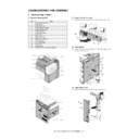
Upper door unit
1)
Remove the front cabinet.
2)
Remove the sprig. Remove the pressure release axis holder
and the screw, and remove the pressure release link lever.
and the screw, and remove the pressure release link lever.
3)
Remove the resin E-ring, and remove the upper door unit.
(5)
Document feed tray
1)
Remove the front cabinet.
2)
Remove the rear cabinet.
3)
Disconnect the connector. Remove the screw, and remove the
document feed tray.
document feed tray.
(6)
Document feed unit
1)
Remove the front cabinet.
2)
Remove the rear cabinet.
3)
Remove the screw. Remove the paper feed cover.
4)
Disconnect the connector. Open the wire saddle. Remove the
snap band.
snap band.
5)
Remove the screw, and remove the document feed unit.
2
4
1
3
1
2
1
1
3
2
2
2
1
2
1
2
2
3
2
1
1
MX-7500N DISASSEMBLY AND ASSEMBLY 10 – 9
(7)
Lamp unit
1)
Remove the front cabinet.
2)
Remove the rear cabinet.
3)
Open the OC mat.
4)
Disconnect the connector for lamp unit from the CONTROL
PWB
PWB
5)
Open the lower door. Remove the screw, and remove the ful-
crum plate. Remove the lower door.
crum plate. Remove the lower door.
6)
Remove the screw, and remove the fulcrum plate. Remove the
white reference plate.
white reference plate.
7)
Remove the screw, and remove the lamp unit.
(8)
Optical unit
1)
Remove the upper door.
2)
Remove the lamp unit.
3)
Remove the screw, and remove the paper guide.
1
4
3
2
2
1
3
2
1
1
2
3
MX-7500N DISASSEMBLY AND ASSEMBLY 10 – 10
4)
Remove the screw, and remove the harness cover. Disconnect
the connector.
the connector.
CAUTION: When assembling, arrange the harness so that it height
is lower than the rib height.
5)
Remove the screw, and remove the optical fixing plate.
Remove the optical unit.
Remove the optical unit.
(9)
Drive unit
1)
Remove the rear cabinet.
2)
Disconnect the connector. Remove the clutch stopper, and
remove the No.1 registration roller clutch.
remove the No.1 registration roller clutch.
CAUTION: When assembling, check to confirm that the clutch stop-
per section is engaged with the plate.
3)
Disconnect the connector, and open the edge saddle. Remove
the snap band.
the snap band.
4)
Remove the screw, and remove the drive unit.
(10) Transport drive unit
1)
Remove the rear cabinet.
2)
Disconnect the connector. Remove the clutch stopper, and
remove the No.1 registration roller clutch.
remove the No.1 registration roller clutch.
CAUTION: When assembling, check to confirm that the clutch stop-
per section is engaged with the plate.
1
2
3
3
4
1
2
2
3
3
2
1
2
3
1
1
2
1
2
1
1
1
3
2
1
MX-7500N DISASSEMBLY AND ASSEMBLY 10 – 11
3)
Disconnect the connector, and remove the snap band.
Remove the resin E-ring, and remove the transport roller
clutch.
Remove the resin E-ring, and remove the transport roller
clutch.
CAUTION: When assembling, check to confirm that the clutch stop-
per section is engaged with the plate.
4)
Disconnect the connector. Remove the screw, and remove the
DSPF cooling fan.
DSPF cooling fan.
5)
Loosen the screw, and loosen the belt tension. Tighten the
screw.
screw.
6)
Disconnect the connector. Remove the screw, and remove the
drive transport unit.
drive transport unit.
(11) DSPF driver PWB
1)
Remove the rear cabinet.
2)
Disconnect the connector. Remove the screw, and remove the
DSPF driver PWB.
DSPF driver PWB.
(12) DSPF control PWB
1)
Remove the rear cabinet.
2)
Disconnect the connector, and remove the screw. Remove the
control PWB unit.
control PWB unit.
3)
Disconnect the connector, and remove the screw. Remove the
DSPF control PWB.
DSPF control PWB.
2
1
3
4
1
2
3
1
1
2
2
2
2
1
2
3
Click on the first or last page to see other MX-6500N / MX-7500N (serv.man24) service manuals if exist.

