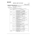
Sharp MX-6500N / MX-7500N (serv.man14) Service Manual ▷ View online
MX-7500N NOTE FOR SERVICING - iii
5.
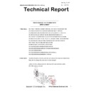
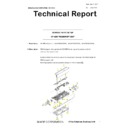
Note for repairing/replacing the LSU
When repairing or replacing, be sure to observe the following
items.
items.
- When repairing or replacing the LSU, be sure to disconnect the
power plug from the power outlet.
- When repairing or replacing the LSU, follow the procedures
described in this Service Manual.
- When checking the operations after repairing the LSU, keep all
the parts including the cover installed and perform the operation
check.
check.
- Do not modify the LSU.
- When visually checking the inside of the machine for the opera-
tion check, be careful not to allow laser beams to enter the eyes.
If the above precaution is neglected or the LSU is modified, ones
safety may be at risk.
safety may be at risk.
6.
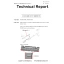
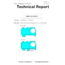
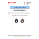
Note for handling the drum unit, the
transfer unit, the developing unit
transfer unit, the developing unit
When handling the OPC drum unit, the transfer unit, and the devel-
oping unit, strictly observe the following items.
oping unit, strictly observe the following items.
If these items are neglected, a problem may be generated in the
copy and print image quality.
copy and print image quality.
Drum unit
- Avoid working at a place with strong lights.
- Do not expose the OPC drum to lights including interior lights for
a long time.
- When the OPC drum is removed from the machine, cover it with
light blocking material. (When using paper, use about 10 sheets
of paper to cover it.)
of paper to cover it.)
- Be careful not to attach fingerprints, oil, grease, or other foreign
material on the OPC drum surface.
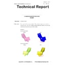
Transfer unit
- Be careful not to leave fingerprints, oil, grease, or other foreign
material on the transfer roller, primary transfer belt, and the sec-
ondary transfer belt.
ondary transfer belt.
Developing unit
- Be careful not to leave fingerprints, oil, grease, or other foreign
material on the developing unit.
Fusing unit
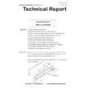
- Be careful not to attach finger prints or foreign materials on the
fusing belt and the pressure roller.
7.
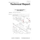
Screw tightening torque
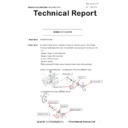
The screws used in this machine are largely classified into three
types.
types.
These types are classified according to the shape of the screw
grooves and use positions.
grooves and use positions.
The table below shows the types of the screws and the tightening
torques depending on the use position.
torques depending on the use position.
When tightening the screws for repair or maintenance, refer to the
table.
table.
However, for the other conditions of tightening screws than speci-
fied on this table, or under special circumstances, the details are
described on the separate page. Refer to the descriptions on such
an exception.
fied on this table, or under special circumstances, the details are
described on the separate page. Refer to the descriptions on such
an exception.
Especially for the screw fixing positions where there is an electrode
or a current flows, use enough care to tighten securely to avoid
loosening.
or a current flows, use enough care to tighten securely to avoid
loosening.
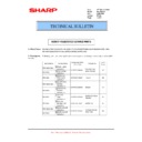
Screw kinds and tightening torques
Normal screws, set screws (including step screws)
Tapping screws (for iron)
Tapping screw (for plastic)
Screw
diameter
Material to be
fixed
Tightening
torque
(N
m)
Tightening
torque
(kgf
cm)
Tightening
torque
(lbft)
M2.6
Steel plate
0.8 - 1.0
8 - 10
0.6 - 0.7
M3
Steel plate
1.0 - 1.2
10 - 12
0.7 - 0.9
M4
Steel plate
1.6 - 1.8
16 - 18
1.2 - 1.3
Screw
diameter
Material to be
fixed
Tightening
torque
(N
m)
Tightening
torque
(kgf
cm)
Tightening
torque
(lbft)
M3
Steel plate
(Plate thickness
0.8mm or above)
1.0 - 1.2
10 - 12
0.7 - 0.9
M4
Steel plate
(Plate thickness
0.8mm or above)
1.6 - 1.8
16 - 18
1.2 - 1.3
M3
Steel plate
(Plate thickness
less than 0.8mm)
0.6 - 0.8
6 - 8
0.4 - 0.6
M4
Steel plate
(Plate thickness
less than 0.8mm)
1.2 - 1.4
12 - 14
0.9 - 1.0
Screw
diameter
Material to be
fixed
Tightening
torque
(N
m)
Tightening
torque
(kgf
cm)
Tightening
torque
(lbft)
M3
Plastic resin
0.6 - 0.8
6 - 8
0.4 - 0.6
M4
Plastic resin
1.0 - 1.2
10 - 12
0.7 - 0.9
Display

