Sharp MX-5500N / MX-6200N / MX-7000N (serv.man68) Service Manual ▷ View online
MX-7000N DRIVE SECTION Q – 6
9)
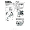
Remove the screws (O), and remove the flywheel (P).
* When installing, check to confirm that has not come in con-
* When installing, check to confirm that has not come in con-
tact with the harness etc.
10) Disconnect the connectors (Q).
11) Disconnect the connectors (R), and the connectors (S).
Remove the screws (T), and remove the main drive unit (BK)
(U).
* When connecting the connectors (S), refer to the mark (V)
(U).
* When connecting the connectors (S), refer to the mark (V)
and connect it.
a. Developement drive motor_K
1)
Remove the rear cabinet. (Refer to the "[A] EXTERNAL OUT-
FIT".)
FIT".)
2)
Remove the screws (A), and open the control box (B).
3)
Remove the screws (C), and remove the flywheel (D).
* When installing, check to confirm that has not come in con-
* When installing, check to confirm that has not come in con-
tact with the harness etc.
O
P
O
Q
Q
T
U
1
S
R
R
V
Unit
Parts
1
Main drive unit (BK)
a
Developement drive motor_K
1-a
B
B
A
A
C
D
C
MX-7000N DRIVE SECTION Q – 7
4)
Disconnect the connectors (E). Remove the screws (F). Disen-
gage the pawl (G) of PWB supporter, and remove the devel-
opement drive motor_K (H).
gage the pawl (G) of PWB supporter, and remove the devel-
opement drive motor_K (H).
b. Developement drive motor
1)
Remove the rear cabinet. (Refer to the "[A] EXTERNAL OUT-
FIT".)
FIT".)
2)
Remove the screws (A), and open the control box (B).
3)
Remove the screws (C), and remove the flywheel (D).
* When installing, check to confirm that has not come in con-
* When installing, check to confirm that has not come in con-
tact with the harness etc.
4)
Disconnect the connector (E). Remove the screws (F), and
remove the transfer drive motor (G).
remove the transfer drive motor (G).
c. Drum motor_K
1)
Remove the rear cabinet. (Refer to the "[A] EXTERNAL OUT-
FIT".)
FIT".)
Unit
Parts
1
Main drive unit (BK)
b
Developement drive motor
E
E
F
F
F
F
H
1-a
G
1-b
B
B
A
A
Unit
Parts
1
Main drive unit (BK)
c
Drum motor_K
C
D
C
F
F
E
G
1-b
1-c
MX-7000N DRIVE SECTION Q – 8
2)
Remove the screws (A), and open the control box (B).
3)
Remove the screws (C), and remove the flywheel (D).
* When installing, check to confirm that has not come in con-
* When installing, check to confirm that has not come in con-
tact with the harness etc.
4)
Disconnect the connector (E). Remove the screws (F), and
remove the drum drive motor_K (G).
remove the drum drive motor_K (G).
d. Belt separation clutch (normal), Belt separation clutch
(reverse)
1)
Remove the rear cabinet. (Refer to the "[A] EXTERNAL OUT-
FIT".)
FIT".)
2)
Remove the screws (A), and open the control box (B).
3)
Remove the screws (C), and remove the flywheel (D).
* When installing, check to confirm that has not come in con-
* When installing, check to confirm that has not come in con-
tact with the harness etc.
B
B
A
A
C
D
C
E
F
F
G
1-c
Unit
Parts
1
Main drive unit (BK)
d
Belt separation clutch (normal)
e
Belt separation clutch (reverse)
1-e
1-d
B
B
A
A
C
D
C
MX-7000N DRIVE SECTION Q – 9
4)
Remove the E-ring (E), and remove the separation drive gear
(F) and the parallel pin (G).
(F) and the parallel pin (G).
5)
Disconnect the connectors (H). Remove the harness from the
wire saddles (I). Remove the belt separation clutch (normal)
(J) and the belt separation clutch (reverse) (K).
wire saddles (I). Remove the belt separation clutch (normal)
(J) and the belt separation clutch (reverse) (K).
e. K phase detection
1)
Remove the rear cabinet. (Refer to the "[A] EXTERNAL OUT-
FIT".)
FIT".)
2)
Remove the screws (A), and open the control box (B).
3)
Remove the screws (C), and remove the flywheel (D).
* When installing, check to confirm that has not come in con-
* When installing, check to confirm that has not come in con-
tact with the harness etc.
4)
Remove the screw (E). Remove the mounting plate (F). Dis-
connect the connector (G), and remove the K phase detection
(H).
connect the connector (G), and remove the K phase detection
(H).
Unit
Parts
1
Main drive unit (BK)
f
K phase detection
E
F
G
H
I
K
I
I
H
1-e
I
J
1-d
1-f
B
B
A
A
C
D
C
E
H
G
F
1-f
Click on the first or last page to see other MX-5500N / MX-6200N / MX-7000N (serv.man68) service manuals if exist.

