Sharp MX-5500N / MX-6200N / MX-7000N (serv.man47) Service Manual ▷ View online
MX-7000N SELF DIAG AND TROUBLE CODE 8 – 3
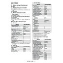
{
: Operation enabled, ✕: Operation disabled
U 1: The operation is enabled in a line other than the trouble line.
U 3: When detected during other than a job, the operation is enabled with a tray other than the trouble tray.
U 4: When detected during other than a job, the operation is enabled in a section other than the trouble paper exit section.
U 5: When detected during other than a job, the operation is enabled in a section other than the inserter connection paper exit port.
U 6: When detected during other than a job, the operation is enabled in the OC mode.
U 7: When detected during other than a job, the operation is enabled in the single surface scan mode.
* 9: When the color mode is set to Disable in the "Color mode disable setting" of the system setting, the operation is enabled in the Black
mode.
* 10: Since communication is enabled, reception can be transferred.
* 12: Trouble display message is displayed in 2 lines. (Example: Ready to copy. F2 trouble)
* 13: When FIERY option is installed, PCL will not operate. (Machine specifications) (Exclusive)
* 14: Only FIERY option list print (self print) is disabled.
* Trouble mode process
• Machine operation enabled under some conditions.
The operations excluding the trouble mode are enabled (READY). For the mode where operations are disabled, only setting is enabled and
the operation disable message is made.
(NOT READY)
(Display) A dialog is displayed when a trouble occurs. For the mode where operations are enabled, [OK] button is added to the message.
When operations are disabled, [OK] button is not displayed, and the message is displayed until the trouble is cancelled.
* For U 1, 3, 5, 6, 7, perform the following procedures. (In order to avoid patent interference.)
• When a trouble is detected during a job, the machine operation is terminated. (Trouble display/without [OK] key)
• When a trouble is detected during other than a JOB, the trouble display is not made and the trouble position cannot be selected. (The dis-
play is not turned off. Machine/Button)
• Troubles which disable the machine operations
The trouble display is always made, and all the modes cannot be set.
• Writing to the trouble memory
Writing of a same trouble to the trouble memory can be selected with SIM26-35. When this simulation is set, any trouble is written to the trou-
ble memory unconditionally.
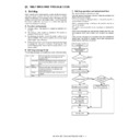
(Sim26-35)
0: Only once. If same as the previous one, it is not saved. (Default)
1: Any time. Though same as the previous one, it is saved.
ble memory unconditionally.
(Sim26-35)
0: Only once. If same as the previous one, it is not saved. (Default)
1: Any time. Though same as the previous one, it is saved.
Connection trouble (SCU
detection)
detection)
SCU
E7 (70, 75),
A0 (22)
A0 (22)
✕
✕
✕
✕
✕
✕
✕
✕
✕
SCU color system
troubles
troubles
UC (02)
✕
✕
✕
✕
✕
{
{
{
{
Document control trouble
UC (20)
✕
✕
✕
✕
✕
{
{
{
{
EEPROM system
U2 (80, 81)
✕
✕
✕
✕
✕
{
{
{
{
Scanner section troubles
(mirror motor, lens, copy
lamp)
(mirror motor, lens, copy
lamp)
L1, L3
✕
✕
✕
✕
✕
{
{
{
{
CCD troubles (shading,
etc.)
etc.)
E7 (10, 11, 14)
✕
✕
✕
✕
✕
{
{
{
{
DSPF trouble
U5
U 6
U 6
U 6
U 6
U 6
{
{
{
{
DSPF back surface CCD
troubles (shading, etc.)
troubles (shading, etc.)
E6 (10, 11, 14)
U 7
U 7
U 7
U 7
U 7
{
{
{
{
Process control trouble
(Only history is left.) (MFP
detection)
(Only history is left.) (MFP
detection)
MFP
F2 (80 – 87, 90)
{
{
{
{
{
{
{
{
{
Process control trouble
(Only history is left.) (PCU
detection)
(Only history is left.) (PCU
detection)
PCU
F2 (92 – 94)
{
{
{
{
{
{
{
{
{
Kind of trouble
Judgment
block
Trouble code
Operatable mode
Copy scan
(including
interruption)
Scan
push
push
Scan pull
Scan
To
HDD
FAX
send
FAX
print
Print
List
print
Notification
to FAST
host
MX-7000N SELF DIAG AND TROUBLE CODE 8 – 4
(2) Power ON trouble detection sequence.
• When the power is turned ON and each trouble of H3, H4, H5, U1, U2, U6 (09) is stored, it is judged as a trouble immediately.
* For A0 and E7 troubles (connection troubles), only the connection trouble information is saved, and they are not regarded as save troubles.
* For A0 and E7 troubles (connection troubles), only the connection trouble information is saved, and they are not regarded as save troubles.
(There is no way to delete the communication trouble information.) (Detected every time when the power is turned ON.)
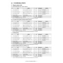
2. Trouble code list
Trouble code
Trouble code content
Remarks
Trouble
detection
Mechanism
Option
Electricity
FAX
Supply
Main
code
code
Sub
code
A0
01
PCU ROM abnormality
MFP
●
02
SCU ROM abnormality
MFP
●
10
Controller ROM error
MFP
●
11
IF version discrepancy (CTL-PCU)
MFP
●
12
IF version discrepancy (CTL-SCU)
MFP
●
20
Machine level error (CTL detection)
MFP
●
21
Machine level error (PCU detection)
PCU
●
22
Machine level error (SCU detection)
SCU
●
C1
01
Charger cleaner trouble
PCU
●
02
Charger cleaner motor lock
PCU
●
C4
00
PTC (Pre-Transfer Charger) high voltage output trouble
PCU
●
01
PTC (Pre-Transfer Charger) cleaner trouble
PCU
●
CE
00
Communication error other than CE-01 – 08
The trouble
code is not
displayed,
but only the
message for
each trouble
is displayed.
code is not
displayed,
but only the
message for
each trouble
is displayed.
MFP
●
01
Network controller trouble
MFP
●
02
Not-specified mail/FTP server error
MFP
●
03
Communication error in image send
MFP
●
04
FTP server account name or authentication password input
error
error
MFP
●
05
FTP server directory input error
MFP
●
06
POP3 server access error
MFP
●
07
POP3 server authentication check error
MFP
●
08
POP3 server timeout error
MFP
●
E6
10
Back-face shading trouble (Black correction) (DSPF)
SCU
●
11
Shading trouble (White correction) (DSPF)
SCU
●
14
Back-face SCAN-ASIC trouble (DSPF)
SCU
●
E7
00
System memory access error
MFP
●
01
System data trouble
MFP
●
03
HDD trouble
MFP
●
04
HDD-ASIC trouble (DSK model only)
MFP
●
05
Local memory access error
MFP
●
(To the corresponding
block)
block)
MFP event
manager
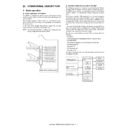
Communication of trouble status
[Trouble code] [Trouble status]
[Trouble code] [Trouble status]
sim task
Trouble cancel command
Trouble cancel status is communicated.
Each block
When the power is turned on,
check is made in each block.
check is made in each block.
Trouble cancel
(The trouble memory is
initialized.)
(The trouble memory is
initialized.)
(Power ON sequence)
·
H3, H4, U1, U2, U6 trouble check
(Trouble cancel sequence)
·
When executing SIM 13, 14, 15, 16
Trouble check is made in each block when initializing
and data are sent to the MFPcnt.
and data are sent to the MFPcnt.
H3, H4, H5: Saved in the MFPcnt.
U1: Saved in the MFPcnt.
U2: Saved in each block.
U6-09: Saved in the PCU.
U1: Saved in the MFPcnt.
U2: Saved in each block.
U6-09: Saved in the PCU.
SIM 13: U1 trouble cancel
SIM 14: H3, H4, H5 (Color mode
SIM 14: H3, H4, H5 (Color mode
cancel)
SIM 15: LCC (U6) trouble cancel
SIM 16: U2 trouble cancel
SIM 16: U2 trouble cancel
MX-7000N SELF DIAG AND TROUBLE CODE 8 – 5
E7
06
Decode error trouble: Compression decode error
(A compression file cannot decompressed.)
(A compression file cannot decompressed.)
MFP
●
09
Local memory combination error
MFP
●
10
Shading trouble (Black correction)
SCU
●
11
Shading trouble (White correction)
SCU
●
14
SCAN-ASIC trouble
SCU
●
20
LSU BD detection trouble
PCU
●
21
LSU LD deterioration trouble
PCU
●
28
LSU control ASIC connection abnormality
PCU
●
29
LSU-ASIC frequency abnormality
PCU
●
50
Engine connection trouble
PCU
●
60
Controller connection trouble (Engine detection)
MFP
●
61
Controller connection trouble (Engine)
MFP
●
62
Controller connection trouble (Scanner)
MFP
●
65
PWB information sum error (Controller detection)
MFP
●
70
Scanner connection trouble
SCU
●
75
PWB information sum error (Scanner detection)
SCU
●
80
Communication trouble between the MFP and the scanner
(MFP detection)
(MFP detection)
MFP
●
90
Communication trouble between the MFP and the PCU
(MFP detection)
(MFP detection)
MFP
●
EE
EC
Auto developer adjustment trouble (The sample level for
every rotation is other than 128
every rotation is other than 128
± 10.)
PCU
●
EL
Auto developer adjustment trouble (Overtoner abnormality)
PCU
●
EU
Auto developer adjustment trouble (Under-toner
abnormality)
abnormality)
PCU
●
F1
00
Finisher communication trouble (Machine side detection)
PCU
●
03
Finisher oscillation motor trouble
PCU
●
08
Finisher stapler shift motor trouble
PCU
●
10
Finisher staple motor abnormality
PCU
●
15
Finisher tray lift motor abnormality
PCU
●
19
Finisher pre-alignment motor abnormality
PCU
●
20
Finisher after-alignment motor abnormality
PCU
●
21
Finisher interface fan motor abnormality
PCU
●
22
Finisher rear edge assist motor trouble
PCU
●
23
Shutter trouble
PCU
●
30
Communication trouble between the finisher and the saddle
PCU
●
31
Finisher folding motor trouble
PCU
●
32
Communication trouble between the finisher and the punch
unit
unit
PCU
●
33
Finisher punch shift motor trouble
PCU
●
34
Finisher punch motor trouble
PCU
●
37
Finisher backup RAM trouble
PCU
●
38
Finisher punch backup RAM trouble
PCU
●
41
Positioning plate motor trouble
PCU
●
42
Guide motor trouble
PCU
●
43
Side alignment motor trouble
PCU
●
44
Stitch motor rear trouble
PCU
●
45
Stitch motor front trouble
PCU
●
46
Paper pushing motor trouble
PCU
●
50
Finisher incompatibility trouble
PCU
●
51
Sensor connector connection trouble
PCU
●
52
Micro SW trouble
PCU
●
60
Communication trouble between the finisher and the
inserter
inserter
PCU
●
61
Inserter EEPROM trouble
PCU
●
62
Inserter reverse sensor trouble
PCU
●
F2
02
Toner supply abnormality (K2)
PCU
●
04
Toner cartridge improper (K2)
PCU
●
05
Toner cartridge CRUM error (K2)
PCU
●
39
Process thermistor trouble
PCU
●
40
Toner empty sensor abnormality (K)
PCU
●
41
Toner empty sensor abnormality (C)
PCU
●
42
Toner empty sensor abnormality (M)
PCU
●
43
Toner empty sensor abnormality (Y)
PCU
●
44
Black exclusive image density sensor trouble (Transfer belt
surface reflection ratio abnormality)
surface reflection ratio abnormality)
PCU
●
45
Color exclusive image density sensor trouble (Calibration
plate surface reflection ratio abnormality)
plate surface reflection ratio abnormality)
PCU
●
49
LSU thermistor trouble
PCU
●
Trouble code
Trouble code content
Remarks
Trouble
detection
Mechanism
Option
Electricity
FAX
Supply
Main
code
code
Sub
code
MX-7000N SELF DIAG AND TROUBLE CODE 8 – 6
F2
50
K phase sensor sensing trouble
PCU
●
51
CL phase sensor sensing trouble (C)
PCU
●
52
CL phase sensor sensing trouble (M)
PCU
●
53
CL phase sensor sensing trouble (Y)
PCU
●
58
Process humidity sensor trouble
PCU
●
64
Toner supply abnormality (K)
PCU
●
65
Toner supply abnormality (C)
PCU
●
66
Toner supply abnormality (M)
PCU
●
67
Toner supply abnormality (Y)
PCU
●
70
Toner cartridge improper (K)
PCU
●
71
Toner cartridge improper (C)
PCU
●
72
Toner cartridge improper (M)
PCU
●
73
Toner cartridge improper (Y)
PCU
●
74
Toner cartridge CRUM error (K)
PCU
●
75
Toner cartridge CRUM error (C)
PCU
●
76
Toner cartridge CRUM error (M)
PCU
●
77
Toner cartridge CRUM error (Y)
PCU
●
78
Registration exclusive image density sensor trouble
(Transfer belt surface reflection ratio abnormality)
(Transfer belt surface reflection ratio abnormality)
PCU
●
80
Half tone process control 1st patch reference value trouble
(K)
(K)
MFP
●
81
Half tone process control 1st patch reference value trouble
(C)
(C)
MFP
●
82
Half tone process control 1st patch reference value trouble
(M)
(M)
MFP
●
83
Half tone process control 1st patch reference value trouble
(Y)
(Y)
MFP
●
84
Half tone process control 2nd patch reference value trouble
(K)
(K)
MFP
●
85
Half tone process control 2nd patch reference value trouble
(C)
(C)
MFP
●
86
Half tone process control 2nd patch reference value trouble
(M)
(M)
MFP
●
87
Half tone process control 2nd patch reference value trouble
(Y)
(Y)
MFP
●
92
High-density process control density correction error (C)
PCU
●
93
High-density process control density correction error (M)
PCU
●
94
High-density process control density correction error (Y)
PCU
●
F3
12
Tray 1 lift-up trouble
PCU
●
22
Tray 2 lift-up trouble
PCU
●
32
Tray 3 lift-up trouble
PCU
●
42
Tray 4 lift-up trouble
PCU
●
F6
00
Communication trouble between the MFP and the FAX
Refer to FAX manual for details
01
FAX board EEPROM read/write error
04
FAX MODEM operation trouble
21
Combination error between the TEL/LIU PWB and the FAX
soft switch
soft switch
30
Access error to power controller on the FAX board (FAX
detection)
detection)
97
FAX PWB incompatibility trouble
98
Combination error between the FAX-BOX PWB destination
information and the machine destination information.
information and the machine destination information.
F9
00
Communication trouble between the controller and the
printer controller (FIERY option)
printer controller (FIERY option)
MFP
●
H2
00
Detection thermistor open (TH1_AD2) of the non-contact
thermistor
thermistor
PCU
01
Lower thermistor open (TH_LM)
PCU
●
02
Sub thermistor open (TH_US)
PCU
●
03
Non-contact thermistor compensation thermistor open
(TH1_AD1)
(TH1_AD1)
PCU
●
04
External heating thermistor open (TH_EX1)
PCU
●
05
Fusing external heating thermistor open (TH_EX2)
PCU
●
H3
00
Fusing section high temperature trouble (TH_UM)
PCU
●
01
Fusing section high temperature trouble (TH_LM)
PCU
●
02
Sub thermistor fusing section high temperature trouble
(TH_US)
(TH_US)
PCU
●
04
External heating thermistor high temperature trouble
(TH_EX1)
(TH_EX1)
PCU
●
05
Fusing external thermistor high temperature trouble
(TH_EX2)
(TH_EX2)
PCU
●
H4
00
Fusing section low temperature trouble (TH_UM_AD2)
PCU
●
Trouble code
Trouble code content
Remarks
Trouble
detection
Mechanism
Option
Electricity
FAX
Supply
Main
code
code
Sub
code

