|
|
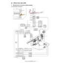
MX-4100N MX-4101N MX-5000N MX-5001N (serv.man6)
MX5001N - Circuit Diagrams
Service Manual
|
127
|
22.85 MB
|
|
|
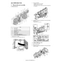
MX-4100N MX-4101N MX-5000N MX-5001N (serv.man7)
Service Manual-Front and Back Covers
Service Manual
|
5
|
257.65 KB
|
|
|
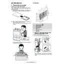
MX-4100N MX-4101N MX-5000N MX-5001N (serv.man8)
Service Manual-Note for Servicing
Service Manual
|
2
|
203.59 KB
|
|
|
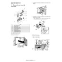
MX-4100N MX-4101N MX-5000N MX-5001N (serv.man9)
Service Manual-Section 1-Product Outline
Service Manual
|
2
|
420.69 KB
|
|
|
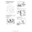
MX-4100N MX-4101N MX-5000N MX-5001N (serv.man10)
Service Manual-Section 2-Specifications
Service Manual
|
9
|
402.75 KB
|
|
|
MX-4100N MX-4101N MX-5000N MX-5001N (serv.man11)
Service Manual-Section 3-Consumable Parts
Service Manual
|
6
|
176.23 KB
|
|
|
MX-4100N MX-4101N MX-5000N MX-5001N (serv.man12)
Service Manual-Section 4-External View And Internal Structure
Service Manual
|
19
|
4.91 MB
|
|
|
MX-4100N MX-4101N MX-5000N MX-5001N (serv.man13)
Service Manual-Section 5-Adjustments
Service Manual
|
105
|
7.25 MB
|
|
|
MX-4100N MX-4101N MX-5000N MX-5001N (serv.man14)
Service Manual-Section 6-Simulations
Service Manual
|
127
|
1.88 MB
|
|
|
MX-4100N MX-4101N MX-5000N MX-5001N (serv.man15)
Service Manual-Section 7-Self Diag and Trouble Code
Service Manual
|
28
|
329.5 KB
|
|
|
MX-4100N MX-4101N MX-5000N MX-5001N (serv.man16)
Service Manual-Section 8-Maintenance
Service Manual
|
47
|
19.24 MB
|
|
|
MX-4100N MX-4101N MX-5000N MX-5001N (serv.man17)
Service Manual-Section 9-Firmware Update
Service Manual
|
4
|
768.45 KB
|
|
|
MX-4100N MX-4101N MX-5000N MX-5001N (serv.man18)
Service Manual-Section 10-Electrical Section
Service Manual
|
41
|
965.32 KB
|
|
|
MX-4100N MX-4101N MX-5000N MX-5001N (serv.man19)
Service Manual-Section 11-Others
Service Manual
|
7
|
185.43 KB
|
|
|
MX-4100N MX-4101N MX-5000N MX-5001N (serv.man20)
Service Manual-Details Of Each Section-(A)External Outfit
Service Manual
|
3
|
1.05 MB
|
|
|
MX-4100N MX-4101N MX-5000N MX-5001N (serv.man21)
Service Manual-Details Of Each Section-(B)Operation Panel
Service Manual
|
4
|
1000.78 KB
|
|
|
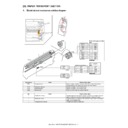
MX-4100N MX-4101N MX-5000N MX-5001N (serv.man22)
Service Manual-Details Of Each Section-(C)DSPF Section
Service Manual
|
12
|
3.02 MB
|
|
|
MX-4100N MX-4101N MX-5000N MX-5001N (serv.man23)
Service Manual-Details Of Each Section-(D)RSPF Section
Service Manual
|
12
|
3.37 MB
|
|
|
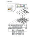
MX-4100N MX-4101N MX-5000N MX-5001N (serv.man24)
Service Manual-Details Of Each Section-(E)Scanner Section
Service Manual
|
5
|
1.07 MB
|
|
|
MX-4100N MX-4101N MX-5000N MX-5001N (serv.man25)
Service Manual-Details Of Each Section-(F)Paper Feed Section
Service Manual
|
9
|
3 MB
|
|
|
MX-4100N MX-4101N MX-5000N MX-5001N (serv.man26)
Service Manual-Details Of Each Section-(G)Paper Transport Section
Service Manual
|
2
|
354.62 KB
|
|
|
MX-4100N MX-4101N MX-5000N MX-5001N (serv.man27)
Service Manual-Details Of Each Section-(H)LSU Section
Service Manual
|
5
|
1.73 MB
|
|
|
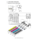
MX-4100N MX-4101N MX-5000N MX-5001N (serv.man28)
Service Manual-Details Of Each Section-(I)Photoconductor Section
Service Manual
|
4
|
1.61 MB
|
|
|
MX-4100N MX-4101N MX-5000N MX-5001N (serv.man29)
Service Manual-Details Of Each Section-(J)Toner Supply Section
Service Manual
|
2
|
710.01 KB
|
|
|
MX-4100N MX-4101N MX-5000N MX-5001N (serv.man30)
Service Manual-Details Of Each Section-(K)Developing Section
Service Manual
|
3
|
1.16 MB
|
|
|
MX-4100N MX-4101N MX-5000N MX-5001N (serv.man32)
Service Manual-Details Of Each Section-(M)Fuser Section
Service Manual
|
6
|
2.85 MB
|
|
|
MX-4100N MX-4101N MX-5000N MX-5001N (serv.man33)
Service Manual-Details Of Each Section-(N)Duplex Paper Exit Section
Service Manual
|
7
|
2.19 MB
|
|
|
MX-4100N MX-4101N MX-5000N MX-5001N (serv.man34)
Service Manual-Details Of Each Section-(O)Drive Section
Service Manual
|
6
|
2.48 MB
|
|
|
MX-4100N MX-4101N MX-5000N MX-5001N (serv.man35)
Service Manual-Details Of Each Section-(P)PWB Section
Service Manual
|
7
|
2.16 MB
|
|
|
MX-4100N MX-4101N MX-5000N MX-5001N (serv.man36)
Service Manual-Details Of Each Section-(Q)Fan Section
Service Manual
|
3
|
1.37 MB
|
|
|
MX-4100N MX-4101N MX-5000N MX-5001N (serv.man37)
Service Manual-Details Of Each Section-(R)Sensor Switch Section
Service Manual
|
2
|
374.96 KB
|
|
|
MX-4100N MX-4101N MX-5000N MX-5001N (serv.man38)
Installation Manual-(Complete Manual)
Service Manual
|
121
|
27.15 MB
|
|
|
MX-4100N MX-4101N MX-5000N MX-5001N (serv.man42)
MX4100-MX5001- Operation Manual
User Manual / Operation Manual
|
127
|
24.53 MB
|

|
MX-4100N MX-4101N MX-5000N MX-5001N
Mac OS10.8 Driver Rquires Postscript option. Mac OS
Drivers
|
|
2.94 MB
|
|
|
MX-4100N MX-4101N MX-5000N MX-5001N (serv.man39)
PWB Parts Guide (Revised November 2014).
Service Manual / Parts Guide
|
60
|
669.04 KB
|
|
|
MX-4100N MX-4101N MX-5000N MX-5001N (serv.man40)
Revised March 2012
Service Manual / Parts Guide
|
127
|
23.05 MB
|
|
|
MX-4100N MX-4101N MX-5000N MX-5001N (serv.man41)
Revised March 2012
Service Manual / Parts Guide
|
60
|
3.68 MB
|
|
|
MX-4100N MX-4101N MX-5000N MX-5001N (serv.man5)
Product Specifications (Taken From Service Manual)
Service Manual / Specification
|
9
|
402.75 KB
|
|
|
MX-4100N MX-4101N MX-5000N MX-5001N (serv.man49)
CCE-1829 MODIFICATION OF PARTS DESIGN
Service Manual / Technical Bulletin
|
2
|
305 KB
|
|
|
MX-4100N MX-4101N MX-5000N MX-5001N (serv.man50)
Parts change for productivity improvement.
Service Manual / Technical Bulletin
|
3
|
184.15 KB
|
|
|
MX-4100N MX-4101N MX-5000N MX-5001N (serv.man51)
Design change of MF Tray 2 Upper.
Service Manual / Technical Bulletin
|
2
|
216.35 KB
|
|
|
MX-4100N MX-4101N MX-5000N MX-5001N (serv.man52)
Modification of drive belt shaft.
Service Manual / Technical Bulletin
|
2
|
68.49 KB
|
|
|
MX-4100N MX-4101N MX-5000N MX-5001N (serv.man53)
Change of TN filter.
Service Manual / Technical Bulletin
|
2
|
132.03 KB
|
|
|
MX-4100N MX-4101N MX-5000N MX-5001N (serv.man54)
Preventing detection of waste toner bottle full.
Service Manual / Technical Bulletin
|
2
|
101.04 KB
|
|
|
MX-4100N MX-4101N MX-5000N MX-5001N (serv.man55)
Change of PPD5 interface harness.
Service Manual / Technical Bulletin
|
2
|
108.01 KB
|
|
|
MX-4100N MX-4101N MX-5000N MX-5001N (serv.man56)
CCE 1508 IMPROVEMENT OF PERFORMANCE WHEN OPENING CLOSING DSPF LOWER DOOR
Service Manual / Technical Bulletin
|
3
|
235.02 KB
|
|
|
MX-4100N MX-4101N MX-5000N MX-5001N (serv.man57)
Design change of delivery paper guide.
Service Manual / Technical Bulletin
|
2
|
91.45 KB
|
|
|
MX-4100N MX-4101N MX-5000N MX-5001N (serv.man58)
Temporary change in containment bag for starting powder.
Service Manual / Technical Bulletin
|
1
|
102.62 KB
|
|
|
MX-4100N MX-4101N MX-5000N MX-5001N (serv.man59)
Starting Powder List (This list takes priority over information in Service Manuals).
Service Manual / Technical Bulletin
|
4
|
66.25 KB
|
|
|
MX-4100N MX-4101N MX-5000N MX-5001N (serv.man60)
DISCONTINUATION OF IDENTIFICATION LABEL OF PROCESS UNIT AND TARGET KIT.
Service Manual / Technical Bulletin
|
1
|
42.37 KB
|
|
|
MX-4100N MX-4101N MX-5000N MX-5001N (serv.man61)
Material change Rotation Plate Sheet.
Service Manual / Technical Bulletin
|
3
|
290.1 KB
|
|
|
MX-4100N MX-4101N MX-5000N MX-5001N (serv.man62)
Recommended shutdown procedure and Power Cycling of MFD
Service Manual / Technical Bulletin
|
1
|
186.43 KB
|
|
|
MX-4100N MX-4101N MX-5000N MX-5001N (serv.man63)
IMPORTANT Handling of EEPROM's.
Service Manual / Technical Bulletin
|
5
|
203.32 KB
|
|
|
MX-4100N MX-4101N MX-5000N MX-5001N (serv.man64)
Enhancement of 1st transfer frame
Service Manual / Technical Bulletin
|
2
|
123.39 KB
|
|
|
MX-4100N MX-4101N MX-5000N MX-5001N (serv.man65)
Change in material of pick up roller.
Service Manual / Technical Bulletin
|
2
|
77.2 KB
|
|
|
MX-4100N MX-4101N MX-5000N MX-5001N (serv.man66)
MODIFICATION OF NOISE GENERATED BY CONTACT BETWEEN TENSION PLATE AND DRIVE TRANSPORT FRAME.
Service Manual / Technical Bulletin
|
2
|
208.65 KB
|
|
|
MX-4100N MX-4101N MX-5000N MX-5001N (serv.man67)
IMPROVEMENT FOR NOISE FROM DV DRIVE MOTOR SECTION OF MAIN DRIVE.
Service Manual / Technical Bulletin
|
3
|
209.98 KB
|
|
|
MX-4100N MX-4101N MX-5000N MX-5001N (serv.man68)
MATERIAL CHANGE WIDTH DETECT SENSOR FIXING PLATE.
Service Manual / Technical Bulletin
|
3
|
229.42 KB
|
|
|
MX-4100N MX-4101N MX-5000N MX-5001N (serv.man69)
Countermeasures against contamination of paper surface.
Service Manual / Technical Bulletin
|
2
|
24.64 KB
|
|
|
MX-4100N MX-4101N MX-5000N MX-5001N (serv.man70)
REMEDY FOR NOISE FROM SECONDARY TRANSFER UNIT.
Service Manual / Technical Bulletin
|
2
|
109.61 KB
|
|
|
MX-4100N MX-4101N MX-5000N MX-5001N (serv.man71)
Treatment for F2-6 Trouble Code.
Service Manual / Technical Bulletin
|
3
|
117.12 KB
|
|
|
MX-4100N MX-4101N MX-5000N MX-5001N (serv.man72)
CHANGE OF MFPC PWB
Service Manual / Technical Bulletin
|
2
|
17.89 KB
|
|
|
MX-4100N MX-4101N MX-5000N MX-5001N (serv.man73)
CHANGE OF HDD DUE TO DISCONTINUANCE OF PRODUCTION.
Service Manual / Technical Bulletin
|
4
|
259.22 KB
|
|
|
MX-4100N MX-4101N MX-5000N MX-5001N (serv.man74)
CCE-1286 COUNTERMEASURE FOR NOISE FROM TN PIPE BK UNIT
Service Manual / Technical Bulletin
|
2
|
126.49 KB
|
|
|
MX-4100N MX-4101N MX-5000N MX-5001N (serv.man75)
CHANGE OF PHOTO SENSOR
Service Manual / Technical Bulletin
|
2
|
111.52 KB
|
|
|
MX-4100N MX-4101N MX-5000N MX-5001N (serv.man76)
IMPROVEMENT OF DETECTION ACCURACY FOR DSPF TRANSPORT UPPER ACTUATOR.
Service Manual / Technical Bulletin
|
2
|
198.78 KB
|
|
|
MX-4100N MX-4101N MX-5000N MX-5001N (serv.man77)
CHANGE OF PHOTO SENSOR.
Service Manual / Technical Bulletin
|
2
|
165.18 KB
|
|
|
MX-4100N MX-4101N MX-5000N MX-5001N (serv.man78)
INCREASE IN MARGIN FOR OPENING AMOUNT OF LSU SHUTTER
Service Manual / Technical Bulletin
|
2
|
325.09 KB
|
|
|
MX-4100N MX-4101N MX-5000N MX-5001N (serv.man79)
IMPROVEMENT FOR TONER MIGRATION IN PROCESS UNIT
Service Manual / Technical Bulletin
|
6
|
402.52 KB
|
|
|
MX-4100N MX-4101N MX-5000N MX-5001N (serv.man80)
Countermeasure for deviation of the hole punch position
Service Manual / Technical Bulletin
|
2
|
35.9 KB
|
|
|
MX-4100N MX-4101N MX-5000N MX-5001N (serv.man81)
ENHANCEMENT TO PREVENT DETACHMENT OF PAPER FEED GUIDE TRANSPORT TOP ACTUATOR
Service Manual / Technical Bulletin
|
2
|
66.52 KB
|
|
|
MX-4100N MX-4101N MX-5000N MX-5001N (serv.man82)
CHANGE OF 8.5-INCH LCD OPERATION PANEL
Service Manual / Technical Bulletin
|
6
|
355.42 KB
|
|
|
MX-4100N MX-4101N MX-5000N MX-5001N (serv.man83)
CCE-1076 WHITE STREAK S DUE TO THE DOCTOR COVER SEAL OR INNER BLADE WEAR.
Service Manual / Technical Bulletin
|
3
|
280.8 KB
|
|
|
MX-4100N MX-4101N MX-5000N MX-5001N (serv.man84)
SOLUTION FOR JAM DUE TO PAPER PASSING BEING UNDETECTED BY PPD2 SENSOR ON PS UNIT (MODELS ADDED TO COUNTERMEASURE)
Service Manual / Technical Bulletin
|
2
|
43.71 KB
|
|
|
MX-4100N MX-4101N MX-5000N MX-5001N (serv.man85)
STRENGTH ENHANCEMENT OF PRIMARY TRANSFER LINK FIXING PLATE
Service Manual / Technical Bulletin
|
2
|
95.37 KB
|
|
|
MX-4100N MX-4101N MX-5000N MX-5001N (serv.man86)
CCE-1112 -COUNTERMEASURE FOR DEVIATION OF PUNCH HOLE POSITION
Service Manual / Technical Bulletin
|
1
|
32.04 KB
|
|
|
MX-4100N MX-4101N MX-5000N MX-5001N (serv.man87)
SUPPORT FOR JAMMING (CPFD1_S1, ETC.) CAUSED BY MISDETECTION OF THE REFLECTION SENSOR OF THE CASSETTE PAPER FEED UNIT.
Service Manual / Technical Bulletin
|
2
|
1.69 MB
|
|
|
MX-4100N MX-4101N MX-5000N MX-5001N (serv.man88)
CHANGE OF MICRO SWITCH AT RSPF PAPER FEED SECTION
Service Manual / Technical Bulletin
|
4
|
151.91 KB
|
|
|
MX-4100N MX-4101N MX-5000N MX-5001N (serv.man89)
CHANGE OF HDD DIMENSIONS VERSUS COMMON MODELS
Service Manual / Technical Bulletin
|
4
|
126.72 KB
|
|
|
MX-4100N MX-4101N MX-5000N MX-5001N (serv.man90)
CHANGE OF SOCKET USED FOR SCANNER
Service Manual / Technical Bulletin
|
2
|
130.89 KB
|
|
|
MX-4100N MX-4101N MX-5000N MX-5001N (serv.man91)
ROM Change MX-FR11U (Commercial Version) V05.01.Jc (Bulletin only)
Service Manual / Technical Bulletin
|
2
|
54.68 KB
|
|
|
MX-4100N MX-4101N MX-5000N MX-5001N (serv.man92)
ROM UPGRADE 05.00.J2 PRODUCTION RUN E00
Service Manual / Technical Bulletin
|
3
|
59.92 KB
|
|
|
MX-4100N MX-4101N MX-5000N MX-5001N (serv.man93)
MX-26-3100 MX-41-5001 MX-41-5112 STRENGTHENING OF DRIVE FRAME LOWER AREA
Service Manual / Technical Bulletin
|
2
|
39.22 KB
|
|
|
MX-4100N MX-4101N MX-5000N MX-5001N (serv.man94)
PREVENTION OF F2-6 ERROR. TONER CARTRIDGE DRIVE AND STORAGE NOTES.
Service Manual / Technical Bulletin
|
3
|
154 KB
|
|
|
MX-4100N MX-4101N MX-5000N MX-5001N (serv.man95)
REVISED TRAY HEATER KIT PROCEDURES.
Service Manual / Technical Bulletin
|
22
|
4.27 MB
|
|
|
MX-4100N MX-4101N MX-5000N MX-5001N (serv.man96)
ACTION FOR NOISE FROM DSPF UPPER AND LOWER TRANSPORT UNITS
Service Manual / Technical Bulletin
|
2
|
420.09 KB
|
|
|
MX-4100N MX-4101N MX-5000N MX-5001N (serv.man97)
DSK ROM UPGRADE ... (5). Ver 04.08.Jc
Service Manual / Technical Bulletin
|
1
|
20.74 KB
|
|
|
MX-4100N MX-4101N MX-5000N MX-5001N (serv.man98)
SHAPE CHANGE TO ACHEIVE PART COMMONALITY INSIDE THE 2ND TRANSFER UNIT
Service Manual / Technical Bulletin
|
2
|
151.55 KB
|
|
|
MX-4100N MX-4101N MX-5000N MX-5001N (serv.man99)
COMMONALITY BETWEEN THE 1ST TRANSFER UNIT AND THE SEPARATOR PAWL
Service Manual / Technical Bulletin
|
4
|
384.74 KB
|
|
|
MX-4100N MX-4101N MX-5000N MX-5001N (serv.man100)
1ST TRANSFER FRAME K, ETC. CHANGE TO PROVIDE COMMONALITY WITH OTHER MODELS
Service Manual / Technical Bulletin
|
2
|
555.65 KB
|
|
|
MX-4100N MX-4101N MX-5000N MX-5001N (serv.man101)
ROM UPGRADE ... (9). Ver 04.07.J2.
Service Manual / Technical Bulletin
|
1
|
30.47 KB
|
|
|
MX-4100N MX-4101N MX-5000N MX-5001N (serv.man102)
KEYBOARD RECOGNITION PROBLEMS DUE TO PROBLEMS IN THE USB CONV PWB FOR THE KEYBOARD.
Service Manual / Technical Bulletin
|
2
|
104.2 KB
|
|
|
MX-4100N MX-4101N MX-5000N MX-5001N (serv.man103)
SUPPORT FOR REVERSE GATE RECOVERY ISSUES OF THE RIGHT DOOR UNIT CAUSING PAPER CORNER FOLDING AND DOUBLE-SIDED JAMS (POD2_S, ETC.)
Service Manual / Technical Bulletin
|
3
|
193.8 KB
|
|
|
MX-4100N MX-4101N MX-5000N MX-5001N (serv.man104)
CREATION OF A PARTS CODE FOR THE MAIN DRIVE MECHANICAL UNIT OF THE 50 PAGE UNIT
Service Manual / Technical Bulletin
|
1
|
81.22 KB
|
|
|
MX-4100N MX-4101N MX-5000N MX-5001N (serv.man105)
DEVELOPER LOSS DUE TO TONER SPLATTER FROM THE BK DEVELOPER TANK
Service Manual / Technical Bulletin
|
2
|
62.62 KB
|
|
|
MX-4100N MX-4101N MX-5000N MX-5001N (serv.man106)
DSK ROM UPGRADE ... (4). Ver 04.06.Jc_A.
Service Manual / Technical Bulletin
|
2
|
25.69 KB
|
|
|
MX-4100N MX-4101N MX-5000N MX-5001N (serv.man107)
CONDUCTIVITY STABILIZATION BETWEEN THE 2ND TC SEPARATE ELECTRODE AND THE 2ND TRANSFER UNIT
Service Manual / Technical Bulletin
|
1
|
46.99 KB
|
|
|
MX-4100N MX-4101N MX-5000N MX-5001N (serv.man108)
IMPROVEMENTS FOR THE PREVENTION OF LEAKING FROM THE PROCESS ELECTRODE COVER
Service Manual / Technical Bulletin
|
2
|
57.72 KB
|
|
|
MX-4100N MX-4101N MX-5000N MX-5001N (serv.man109)
TRANSPORT JAM FROM THE OPTION DESK. (PPD1_S3 etc.)
Service Manual / Technical Bulletin
|
2
|
71.64 KB
|
|
|
MX-4100N MX-4101N MX-5000N MX-5001N (serv.man110)
PART DISCONTINUATION AND PARTS CHANGE FOR THE MULTI-PAPER FEEDING UNIT DUE TO PRODUCTION EFFICIENCY INCREASE
Service Manual / Technical Bulletin
|
2
|
51.56 KB
|
|
|
MX-4100N MX-4101N MX-5000N MX-5001N (serv.man111)
COUNTERMEASURES FOR THE 2ND TRANSFER DRIVING PULLEY BELT COMING LOOSE
Service Manual / Technical Bulletin
|
2
|
88.65 KB
|
|
|
MX-4100N MX-4101N MX-5000N MX-5001N (serv.man112)
ROM UPGRADE ... (8). Ver 04.05.J200_A.
Service Manual / Technical Bulletin
|
2
|
36.58 KB
|
|
|
MX-4100N MX-4101N MX-5000N MX-5001N (serv.man113)
SUPPORT AGAINST BREAKAGE OF EXPOSED LEAD WIRES OF THE CLUTCH
Service Manual / Technical Bulletin
|
2
|
85.31 KB
|
|
|
MX-4100N MX-4101N MX-5000N MX-5001N (serv.man114)
FIX FOR THE NOISE COMING FROM THE BK TONER COOLING FAN
Service Manual / Technical Bulletin
|
2
|
108.32 KB
|
|
|
MX-4100N MX-4101N MX-5000N MX-5001N (serv.man115)
IMPROVED PAPER FEEDING PERFORMANCE FOR PAPER THAT HAS AN OVERLY UPWARD CURL (PDPPD1_N JAMS)
Service Manual / Technical Bulletin
|
1
|
74.45 KB
|
|
|
MX-4100N MX-4101N MX-5000N MX-5001N (serv.man116)
IMPROVEMENTS TO THE DUST-PROOFING OF THE OPTICAL UNIT
Service Manual / Technical Bulletin
|
2
|
147.02 KB
|
|
|
MX-4100N MX-4101N MX-5000N MX-5001N (serv.man117)
JOBS NOT BEING RECORDED IN THE JOB LOG
Service Manual / Technical Bulletin
|
1
|
64.83 KB
|
|
|
MX-4100N MX-4101N MX-5000N MX-5001N (serv.man118)
MALFUNCTION IN THE FUSING PRESSURE RELEASE DETECTOR CAUSING L4-16 ERROR CODE
Service Manual / Technical Bulletin
|
1
|
50.05 KB
|
|
|
MX-4100N MX-4101N MX-5000N MX-5001N (serv.man119)
HID CARD READER SETTING
Service Manual / Technical Bulletin
|
1
|
17.35 KB
|
|
|
MX-4100N MX-4101N MX-5000N MX-5001N (serv.man120)
DSK ROM UPGRADE ... (1) TO (2). Ver 04.02.Jc_A
Service Manual / Technical Bulletin
|
7
|
58.72 KB
|
|
|
MX-4100N MX-4101N MX-5000N MX-5001N (serv.man121)
INCREASE IN VERTICAL TRANSFERABILITY MARGIN OF RIGHT LOWER DOOR
Service Manual / Technical Bulletin
|
2
|
110.65 KB
|
|
|
MX-4100N MX-4101N MX-5000N MX-5001N (serv.man122)
ROM UPGRADE ... (6). Ver 04.01.J200_A.
Service Manual / Technical Bulletin
|
2
|
34.37 KB
|
|
|
MX-4100N MX-4101N MX-5000N MX-5001N (serv.man123)
FIX TO INCREASE THE MARGIN THAT A C4-02 ERROR WILL OCCUR DUE TO A CHANGE IN THE PATTERN OF THE ION PTC ELEMENT
Service Manual / Technical Bulletin
|
2
|
68.54 KB
|
|
|
MX-4100N MX-4101N MX-5000N MX-5001N (serv.man124)
IMPROVEMENTS TO DUST RESISTANCE OF THE DSPF REDUCTION OPTICAL UNIT
Service Manual / Technical Bulletin
|
2
|
122 KB
|
|
|
MX-4100N MX-4101N MX-5000N MX-5001N (serv.man125)
PRECAUTIONS WHEN INSERTING A TONER CARTRIDGE
Service Manual / Technical Bulletin
|
1
|
15.47 KB
|
|
|
MX-4100N MX-4101N MX-5000N MX-5001N (serv.man126)
COUNTERMEASURES AGAINST THE WEB ROLLER SHEET BECOMING WOUND UPON THE OUTER HEAT ROLLER
Service Manual / Technical Bulletin
|
2
|
76.28 KB
|
|
|
MX-4100N MX-4101N MX-5000N MX-5001N (serv.man127)
ROM UPGRADE ... (5)
Service Manual / Technical Bulletin
|
3
|
42.81 KB
|
|
|
MX-4100N MX-4101N MX-5000N MX-5001N (serv.man128)
Operations Required for Machine Movement
Service Manual / Technical Bulletin
|
1
|
14.68 KB
|
|
|
MX-4100N MX-4101N MX-5000N MX-5001N (serv.man129)
INSTALLATION NOTES FOR REPLACING THE SECONDARY TRANSFER BELT
Service Manual / Technical Bulletin
|
1
|
80.58 KB
|
|
|
MX-4100N MX-4101N MX-5000N MX-5001N (serv.man130)
SUPPORT AGAINST SCUFFING THE PHOTORECEPTOR DRUM WHEN PULLING OUT THE DV UNIT
Service Manual / Technical Bulletin
|
2
|
124.91 KB
|
|
|
MX-4100N MX-4101N MX-5000N MX-5001N (serv.man131)
NOTIFICATION OF REVISED DESCRIPTIONS IN THE INSTALLATION MANUAL FOR MX-FR11U (DSK)
Service Manual / Technical Bulletin
|
5
|
341.39 KB
|
|
|
MX-4100N MX-4101N MX-5000N MX-5001N (serv.man132)
BLANK COPIES DUE TO MC PWB RESISTOR
Service Manual / Technical Bulletin
|
2
|
89.56 KB
|
|
|
MX-4100N MX-4101N MX-5000N MX-5001N (serv.man133)
MXDEX9 - COUNTERMEASURES FOR DPFD2_S, etc. CAUSED BY CARRYING FORCE DECREASE BECAUSE OF PAPER POWDERS
Service Manual / Technical Bulletin
|
1
|
26.18 KB
|
|
|
MX-4100N MX-4101N MX-5000N MX-5001N (serv.man134)
IMPROVEMENT AGAINST RATTLING DUE TO SKIPPING ENGAGING-DISENGAGING GEAR TEETH
Service Manual / Technical Bulletin
|
2
|
92.62 KB
|
|
|
MX-4100N MX-4101N MX-5000N MX-5001N (serv.man135)
DAMAGE ON DRUM SURFACE CAUSED WHEN DV UNIT IS PULLED OUT
Service Manual / Technical Bulletin
|
2
|
154.97 KB
|
|
|
MX-4100N MX-4101N MX-5000N MX-5001N (serv.man136)
ISSUING EXPLANATORY MATERIAL OF JOB LOG CODES.
Service Manual / Technical Bulletin
|
13
|
160.14 KB
|
|
|
MX-4100N MX-4101N MX-5000N MX-5001N (serv.man137)
SERVICE PART ADDITION FOR ADDED RELIABILITY OF SHEET SEPARATION FROM THE 1ST TRANSFER BELT
Service Manual / Technical Bulletin
|
3
|
227.06 KB
|
|
|
MX-4100N MX-4101N MX-5000N MX-5001N (serv.man138)
8.5-INCH LCD PANEL ILLUMINATION FAILURE DUE TO IMPROPER WIRING WORK IN THE OPERATING PANEL
Service Manual / Technical Bulletin
|
2
|
146.26 KB
|
|
|
MX-4100N MX-4101N MX-5000N MX-5001N (serv.man139)
ACTION AGAINST DAMAGING THE EXTERNAL HEATING BELT
Service Manual / Technical Bulletin
|
1
|
68.21 KB
|
|
|
MX-4100N MX-4101N MX-5000N MX-5001N (serv.man140)
ABOLISHING LCD MYLAR AB BY CHANGING 8.5-INCH TOUCH PANELS
Service Manual / Technical Bulletin
|
1
|
53.12 KB
|
|
|
MX-4100N MX-4101N MX-5000N MX-5001N (serv.man141)
PRECAUTIONS WHEN INSTALLING KEYBOARD UNIT MX-KBX2
Service Manual / Technical Bulletin
|
1
|
21.23 KB
|
|
|
MX-4100N MX-4101N MX-5000N MX-5001N (serv.man142)
JAM (APPD1_N) RESULTING FROM ADU FOLLOWER ROLLER SPRING COMING-OFF
Service Manual / Technical Bulletin
|
2
|
119.73 KB
|
|
|
MX-4100N MX-4101N MX-5000N MX-5001N (serv.man143)
ROM UPGRADE ... (4)
Service Manual / Technical Bulletin
|
4
|
46.64 KB
|
|
|
MX-4100N MX-4101N MX-5000N MX-5001N (serv.man144)
SIMULATION 55 SETTINGS
Service Manual / Technical Bulletin
|
2
|
53.79 KB
|
|
|
MX-4100N MX-4101N MX-5000N MX-5001N (serv.man145)
CHANGE OF INITIAL VALUES OF PREHEAT MODE AND AUTO POWER SHUT-OFF MODE INVOLVED IN SUPPORT OF ENERGY STAR VER1.1 (TIER II)
Service Manual / Technical Bulletin
|
1
|
27.92 KB
|
|
|
MX-4100N MX-4101N MX-5000N MX-5001N (serv.man146)
CHANGE OF SHAPE OF PROCESS F COVER
Service Manual / Technical Bulletin
|
2
|
45.56 KB
|
|
|
MX-4100N MX-4101N MX-5000N MX-5001N (serv.man147)
ROM UPGRADE ... (3)
Service Manual / Technical Bulletin
|
4
|
62.67 KB
|
|
|
MX-4100N MX-4101N MX-5000N MX-5001N (serv.man148)
HARD DISK DRIVE (HDD) REPLACEMENT PROCEDURE AND NOTES
Service Manual / Technical Bulletin
|
7
|
1.11 MB
|
|
|
MX-4100N MX-4101N MX-5000N MX-5001N (serv.man149)
U5-00 TROUBLE CODE OCCURRENCE RESULTING FROM CATCH OF DSPF TAKE-UP ROLLER
Service Manual / Technical Bulletin
|
2
|
80.28 KB
|
|
|
MX-4100N MX-4101N MX-5000N MX-5001N (serv.man150)
COUNTERMEASURES TO COPE WITH BEAD EROSION, BLADE INVERSION, AND BELT BREAKAGE THAT OCCUR IN 1ST TRANSFER UNIT
Service Manual / Technical Bulletin
|
3
|
145.16 KB
|
|
|
MX-4100N MX-4101N MX-5000N MX-5001N (serv.man151)
L4-31 TROUBLE CODE OCCURRENCE
Service Manual / Technical Bulletin
|
2
|
44.98 KB
|
|
|
MX-4100N MX-4101N MX-5000N MX-5001N (serv.man152)
CHANGES TO 1st TRANSFER BELT ATTACHMENT METHOD
Service Manual / Technical Bulletin
|
2
|
102.62 KB
|
|
|
MX-4100N MX-4101N MX-5000N MX-5001N (serv.man153)
C4-00 TROUBLE CODE OCCURRENCE
Service Manual / Technical Bulletin
|
1
|
25.04 KB
|
|
|
MX-4100N MX-4101N MX-5000N MX-5001N (serv.man154)
INCREASE IN HEAT RESISTANCE MARGIN OF ADIABATIC BUSHING OF FUSING UNIT
Service Manual / Technical Bulletin
|
1
|
38.55 KB
|
|
|
MX-4100N MX-4101N MX-5000N MX-5001N (serv.man155)
COUNTERMEASURES FOR IMAGE BLURRING THAT OCCURS AT TIP OF DOCUMENT WHEN SPF-DSPF IS USED
Service Manual / Technical Bulletin
|
2
|
120.22 KB
|
|
|
MX-4100N MX-4101N MX-5000N MX-5001N (serv.man156)
MX-FN11 ROM UPGRADE ... (1)
Service Manual / Technical Bulletin
|
2
|
29.55 KB
|
|
|
MX-4100N MX-4101N MX-5000N MX-5001N (serv.man157)
PROVISION OF SERVICE PART FOR SOLVING PROBLEM WITH MARK ON COPY PAPER FROM EDGES OF ROLLER
Service Manual / Technical Bulletin
|
1
|
42.28 KB
|
|
|
MX-4100N MX-4101N MX-5000N MX-5001N (serv.man158)
IMPROVEMENT OF DV UNIT TONER LOSS
Service Manual / Technical Bulletin
|
2
|
94.05 KB
|
|
|
MX-4100N MX-4101N MX-5000N MX-5001N (serv.man159)
011 -COUNTERMEASURES FOR BLACK STRIPES RESULTING FROM PAPER POWDER WHEN RSPF IS USED
Service Manual / Technical Bulletin
|
1
|
18.02 KB
|
|
|
MX-4100N MX-4101N MX-5000N MX-5001N (serv.man160)
OCCURRENCE OF ABNORMAL SOUND (SQUEAK) FROM PROCESS UNIT SECTION
Service Manual / Technical Bulletin
|
1
|
54.82 KB
|
|
|
MX-4100N MX-4101N MX-5000N MX-5001N (serv.man161)
MEASURES TO SUPPRESS TEMPERATURE ELEVATION ON BOTH ENDS OF UPPER HEAT ROLLER DURING CONTINUOUS HEAVY PAPER FEEDING
Service Manual / Technical Bulletin
|
1
|
18 KB
|
|
|
MX-4100N MX-4101N MX-5000N MX-5001N (serv.man162)
OCCURRENCE OF TROUBLE CODE E7-20 DUE TO OVERVOLTAGE ON LD PWB
Service Manual / Technical Bulletin
|
1
|
56.76 KB
|
|
|
MX-4100N MX-4101N MX-5000N MX-5001N (serv.man163)
PROVIDING SUFFICIENT MARGIN AGAINST WEARING OF WEB CONTROL GEAR IN FUSING UNIT
Service Manual / Technical Bulletin
|
2
|
65.79 KB
|
|
|
MX-4100N MX-4101N MX-5000N MX-5001N (serv.man164)
CAUTIONARY NOTES ON MAINTENANCE OF FUSING UNIT
Service Manual / Technical Bulletin
|
2
|
146.01 KB
|
|
|
MX-4100N MX-4101N MX-5000N MX-5001N (serv.man165)
HANDLING TROUBLE CODE F2-40 INVOLVING LEAK FROM PROCESS ELECTRODE
Service Manual / Technical Bulletin
|
2
|
130.06 KB
|
|
|
MX-4100N MX-4101N MX-5000N MX-5001N (serv.man166)
HEATER KIT MOUNTING PROCEDURES
Service Manual / Technical Bulletin
|
23
|
4.29 MB
|
|
|
MX-4100N MX-4101N MX-5000N MX-5001N (serv.man167)
PROBLEM C4-02 (PTC HEATER OPEN TROUBLE) IS CAUSED BY POOR CONTACT OF PTC HEATER SPRING
Service Manual / Technical Bulletin
|
2
|
69.42 KB
|
|
|
MX-4100N MX-4101N MX-5000N MX-5001N (serv.man168)
PROBLEM WITH WASTE TONER SHUTTER OPENING CAUSED BY VARIATION IN WASTE TONER SHUTTER HOLDER ASSEMBLY
Service Manual / Technical Bulletin
|
1
|
57.5 KB
|
|
|
MX-4100N MX-4101N MX-5000N MX-5001N (serv.man169)
SIM 55-3 Soft Switch settings
Service Manual / Technical Bulletin
|
2
|
62.79 KB
|
|
|
MX-4100N MX-4101N MX-5000N MX-5001N (serv.man170)
ROM UPGRADE ... (1)
Service Manual / Technical Bulletin
|
2
|
26.46 KB
|

|
MX-4100N MX-4101N MX-5000N MX-5001N (serv.man44)
MX4100 4101 5000 5001 e-manual
Driver / Update
|
|
421.27 MB
|

|
MX-4100N MX-4101N MX-5000N MX-5001N (serv.man45)
MX410x 500xN Combined Firmware Version 05.00.J2. Bulletin Embedded
Driver / Update
|
|
38.28 MB
|

|
MX-4100N MX-4101N MX-5000N MX-5001N (serv.man46)
MX410x 500xN Combined Firmware Version 05.00.J2. For machines fitted with DSK only
Driver / Update
|
|
38.4 MB
|

|
MX-4100N MX-4101N MX-5000N MX-5001N (serv.man47)
PPD2_PRI Jam When Using Citrix Universal Printer
Driver / Update
|
|
6.12 MB
|

|
MX-4100N MX-4101N MX-5000N MX-5001N (serv.man48)
MX4100-5001 Watermark data Ver 01.01.J200. To be used when replacing HDD.
Driver / Update
|
|
6.09 MB
|
|
|
MX-4100N MX-4101N MX-5000N MX-5001N (serv.man2)
EEPROM Programming Procedure
Handy Guide
|
4
|
772.27 KB
|
|
|
MX-4100N MX-4101N MX-5000N MX-5001N (serv.man3)
Revised Handy Guide Version 4 July 2010
Handy Guide
|
48
|
1.08 MB
|
|
|
MX-4100N MX-4101N MX-5000N MX-5001N (serv.man4)
Revised Handyguide Version 2c November 2009
Handy Guide
|
48
|
1.08 MB
|

|
MX-4100N MX-4101N MX-5000N MX-5001N (serv.man43)
UPDATED PJL PCL PS Command Lists
FAQ
|
|
128.84 KB
|

