|
|
MX-3050N MX-3060N MX-3070N MX-3550N MX-3560N MX-3570N MX-4050N MX-4060N MX-4070N (serv.man4)
Circuit Diagram (Revised November 2017).
Service Manual
|
127
|
18.04 MB
|
|
|
MX-3050N MX-3060N MX-3070N MX-3550N MX-3560N MX-3570N MX-4050N MX-4060N MX-4070N (serv.man5)
Service Manual (Revised November 2017).
Service Manual
|
127
|
105.17 MB
|
|
|
MX-3050N MX-3060N MX-3070N MX-3550N MX-3560N MX-3570N MX-4050N MX-4060N MX-4070N (serv.man6)
NOTE Service Manual for models with the V suffix only.
Service Manual
|
127
|
104.48 MB
|
|
|
MX-3050N MX-3060N MX-3070N MX-3550N MX-3560N MX-3570N MX-4050N MX-4060N MX-4070N (serv.man7)
NOTE Installation Manual for models with the V suffix only.
Service Manual
|
127
|
68.84 MB
|
|
|
MX-3050N MX-3060N MX-3070N MX-3550N MX-3560N MX-3570N MX-4050N MX-4060N MX-4070N (serv.man8)
NOTE Circuit Diagram for models with the V suffix only.
Service Manual
|
127
|
15.58 MB
|
|
|
MX-3050N MX-3060N MX-3070N MX-3550N MX-3560N MX-3570N MX-4050N MX-4060N MX-4070N (serv.man9)
Installation Manual (Revised May 2017).
Service Manual
|
127
|
79.83 MB
|
|
|
MX-3050N MX-3060N MX-3070N MX-3550N MX-3560N MX-3570N MX-4050N MX-4060N MX-4070N (serv.man14)
E-manual Firmware Notes for down loading E-manual files and merging files for upload
User Manual / Operation Manual
|
1
|
278.05 KB
|

|
MX-3050N MX-3060N MX-3070N MX-3550N MX-3560N MX-3570N MX-4050N MX-4060N MX-4070N (serv.man15)
Phoenix E-Manual Part 1
User Manual / Operation Manual
|
|
85.83 MB
|

|
MX-3050N MX-3060N MX-3070N MX-3550N MX-3560N MX-3570N MX-4050N MX-4060N MX-4070N (serv.man16)
Phoenix E-Manual Part 2
User Manual / Operation Manual
|
|
85.85 MB
|

|
MX-3050N MX-3060N MX-3070N MX-3550N MX-3560N MX-3570N MX-4050N MX-4060N MX-4070N (serv.man17)
Phoenix E-Manual Part 3
User Manual / Operation Manual
|
|
85.84 MB
|

|
MX-3050N MX-3060N MX-3070N MX-3550N MX-3560N MX-3570N MX-4050N MX-4060N MX-4070N (serv.man18)
Phoenix E-Manual Part 4
User Manual / Operation Manual
|
|
85.85 MB
|

|
MX-3050N MX-3060N MX-3070N MX-3550N MX-3560N MX-3570N MX-4050N MX-4060N MX-4070N (serv.man19)
Phoenix E-Manual part 5
User Manual / Operation Manual
|
|
85.84 MB
|

|
MX-3050N MX-3060N MX-3070N MX-3550N MX-3560N MX-3570N MX-4050N MX-4060N MX-4070N (serv.man20)
Phoenix E-Manual part 6
User Manual / Operation Manual
|
|
85.84 MB
|

|
MX-3050N MX-3060N MX-3070N MX-3550N MX-3560N MX-3570N MX-4050N MX-4060N MX-4070N (serv.man21)
Phoenix E-Manual part 7
User Manual / Operation Manual
|
|
85.84 MB
|

|
MX-3050N MX-3060N MX-3070N MX-3550N MX-3560N MX-3570N MX-4050N MX-4060N MX-4070N (serv.man22)
Phoenix E-Manual part 8
User Manual / Operation Manual
|
|
85.84 MB
|

|
MX-3050N MX-3060N MX-3070N MX-3550N MX-3560N MX-3570N MX-4050N MX-4060N MX-4070N (serv.man23)
Phoenix E-Manual part 9
User Manual / Operation Manual
|
|
85.84 MB
|

|
MX-3050N MX-3060N MX-3070N MX-3550N MX-3560N MX-3570N MX-4050N MX-4060N MX-4070N (serv.man24)
Phoenix E-Manual part 10
User Manual / Operation Manual
|
|
85.84 MB
|

|
MX-3050N MX-3060N MX-3070N MX-3550N MX-3560N MX-3570N MX-4050N MX-4060N MX-4070N (serv.man25)
Phoenix E-Manual part 11
User Manual / Operation Manual
|
|
85.84 MB
|

|
MX-3050N MX-3060N MX-3070N MX-3550N MX-3560N MX-3570N MX-4050N MX-4060N MX-4070N (serv.man26)
Phoenix E-Manual part 12
User Manual / Operation Manual
|
|
85.84 MB
|

|
MX-3050N MX-3060N MX-3070N MX-3550N MX-3560N MX-3570N MX-4050N MX-4060N MX-4070N (serv.man27)
Phoenix E-Manual part 13
User Manual / Operation Manual
|
|
85.85 MB
|

|
MX-3050N MX-3060N MX-3070N MX-3550N MX-3560N MX-3570N MX-4050N MX-4060N MX-4070N (serv.man28)
Phoenix E-Manual part 14 inc. restoration file
User Manual / Operation Manual
|
|
14.54 MB
|
|
|
MX-3050N MX-3060N MX-3070N MX-3550N MX-3560N MX-3570N MX-4050N MX-4060N MX-4070N (serv.man29)
Quick Start Guide PDF
User Manual / Operation Manual
|
60
|
7.85 MB
|
|
|
MX-3050N MX-3060N MX-3070N MX-3550N MX-3560N MX-3570N MX-4050N MX-4060N MX-4070N (serv.man30)
User Manual PDF
User Manual / Operation Manual
|
127
|
58.19 MB
|
|
|
MX-3050N MX-3060N MX-3070N MX-3550N MX-3560N MX-3570N MX-4050N MX-4060N MX-4070N (serv.man31)
Software Setup Guide PDF
User Manual / Operation Manual
|
45
|
2.56 MB
|
|
|
MX-3050N MX-3060N MX-3070N MX-3550N MX-3560N MX-3570N MX-4050N MX-4060N MX-4070N (serv.man32)
Print release Guide PDF
User Manual / Operation Manual
|
10
|
1.11 MB
|
|
|
MX-3050N MX-3060N MX-3070N MX-3550N MX-3560N MX-3570N MX-4050N MX-4060N MX-4070N (serv.man33)
Web Page Guide PDF
User Manual / Operation Manual
|
38
|
3.25 MB
|
|
|
MX-3050N MX-3060N MX-3070N MX-3550N MX-3560N MX-3570N MX-4050N MX-4060N MX-4070N (serv.man34)
UI Customization Guide PDF
User Manual / Operation Manual
|
34
|
5.95 MB
|
|
|
MX-3050N MX-3060N MX-3070N MX-3550N MX-3560N MX-3570N MX-4050N MX-4060N MX-4070N (serv.man35)
Trouble Shooting Guide PDF
User Manual / Operation Manual
|
58
|
1.57 MB
|
|
|
MX-3050N MX-3060N MX-3070N MX-3550N MX-3560N MX-3570N MX-4050N MX-4060N MX-4070N (serv.man10)
PWB Parts Guide for models with the V suffix.
Service Manual / Parts Guide
|
57
|
2.67 MB
|
|
|
MX-3050N MX-3060N MX-3070N MX-3550N MX-3560N MX-3570N MX-4050N MX-4060N MX-4070N (serv.man11)
NOTE Parts Guide for models with the V suffix only.
Service Manual / Parts Guide
|
127
|
157.23 MB
|
|
|
MX-3050N MX-3060N MX-3070N MX-3550N MX-3560N MX-3570N MX-4050N MX-4060N MX-4070N (serv.man12)
Parts Guide (Revised September 2017).
Service Manual / Parts Guide
|
127
|
93.12 MB
|
|
|
MX-3050N MX-3060N MX-3070N MX-3550N MX-3560N MX-3570N MX-4050N MX-4060N MX-4070N (serv.man13)
PWB Parts Guide (Revised June 2016).
Service Manual / Parts Guide
|
40
|
2.3 MB
|
|
|
MX-3050N MX-3060N MX-3070N MX-3550N MX-3560N MX-3570N MX-4050N MX-4060N MX-4070N (serv.man56)
Fuser temperature relating to paper type. Offsetting.
Service Manual / Technical Bulletin
|
1
|
21.65 KB
|
|
|
MX-3050N MX-3060N MX-3070N MX-3550N MX-3560N MX-3570N MX-4050N MX-4060N MX-4070N (serv.man57)
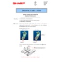
CCE 1847 PARTS MODIFICATION FOR PRODUCTIVITY IMPROVEMENT
Service Manual / Technical Bulletin
|
3
|
278.75 KB
|
|
|
MX-3050N MX-3060N MX-3070N MX-3550N MX-3560N MX-3570N MX-4050N MX-4060N MX-4070N (serv.man58)
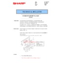
CCE 1847 ADDITION OF HL EDGE PROTECT SHEET
Service Manual / Technical Bulletin
|
2
|
212.95 KB
|
|
|
MX-3050N MX-3060N MX-3070N MX-3550N MX-3560N MX-3570N MX-4050N MX-4060N MX-4070N (serv.man59)
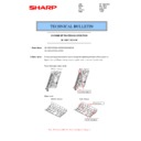
CCE 1793 ADDITION OF HL EDGE PROTECT SHEET
Service Manual / Technical Bulletin
|
2
|
212.69 KB
|
|
|
MX-3050N MX-3060N MX-3070N MX-3550N MX-3560N MX-3570N MX-4050N MX-4060N MX-4070N (serv.man60)
CCE 1732 COUNTERMEASURE FOR RE-TRANSPORT OF MX-FN27
Service Manual / Technical Bulletin
|
4
|
566.57 KB
|
|
|
MX-3050N MX-3060N MX-3070N MX-3550N MX-3560N MX-3570N MX-4050N MX-4060N MX-4070N (serv.man61)
CCE 1714 FIELD ACTION FOR TRAY JAM
Service Manual / Technical Bulletin
|
4
|
389.96 KB
|
|
|
MX-3050N MX-3060N MX-3070N MX-3550N MX-3560N MX-3570N MX-4050N MX-4060N MX-4070N (serv.man62)
CCE 1839 PARTS CHANGE FOR PRODUCTIVITY IMPROVEMENT
Service Manual / Technical Bulletin
|
2
|
169.03 KB
|
|
|
MX-3050N MX-3060N MX-3070N MX-3550N MX-3560N MX-3570N MX-4050N MX-4060N MX-4070N (serv.man63)
CCE 1831 IMPORTANT NOTE WHEN INSTALLING OPTIONS to MX2630 and MX30XX series
Service Manual / Technical Bulletin
|
6
|
611.78 KB
|
|
|
MX-3050N MX-3060N MX-3070N MX-3550N MX-3560N MX-3570N MX-4050N MX-4060N MX-4070N (serv.man64)
CCE 1835 ROM Upgrade (3) DSK V07.00.()1.00 FR51U FR52U Bulletin Only
Service Manual / Technical Bulletin
|
6
|
261.04 KB
|
|
|
MX-3050N MX-3060N MX-3070N MX-3550N MX-3560N MX-3570N MX-4050N MX-4060N MX-4070N (serv.man65)
CCE 1835 ROM Upgrade (13) V07.00.()1.00 Bulletin Only
Service Manual / Technical Bulletin
|
7
|
292.51 KB
|
|
|
MX-3050N MX-3060N MX-3070N MX-3550N MX-3560N MX-3570N MX-4050N MX-4060N MX-4070N (serv.man66)
CCE 1835 PARTS MODIFICATION FOR COMMON USE WITH OTHER MODELS
Service Manual / Technical Bulletin
|
2
|
236.61 KB
|
|
|
MX-3050N MX-3060N MX-3070N MX-3550N MX-3560N MX-3570N MX-4050N MX-4060N MX-4070N (serv.man67)
Box Connector (TLS 1.2) Special Firmware release (Revision)
Service Manual / Technical Bulletin
|
2
|
144.51 KB
|
|
|
MX-3050N MX-3060N MX-3070N MX-3550N MX-3560N MX-3570N MX-4050N MX-4060N MX-4070N (serv.man68)
CCE 1830 Supply of Lamp Unit
Service Manual / Technical Bulletin
|
1
|
175.19 KB
|
|
|
MX-3050N MX-3060N MX-3070N MX-3550N MX-3560N MX-3570N MX-4050N MX-4060N MX-4070N (serv.man69)
CCE-1829 MODIFICATION OF PARTS DESIGN
Service Manual / Technical Bulletin
|
2
|
305 KB
|
|
|
MX-3050N MX-3060N MX-3070N MX-3550N MX-3560N MX-3570N MX-4050N MX-4060N MX-4070N (serv.man70)
CCE-1827 MODIFICATION OF PARTS DESIGN
Service Manual / Technical Bulletin
|
3
|
311 KB
|
|
|
MX-3050N MX-3060N MX-3070N MX-3550N MX-3560N MX-3570N MX-4050N MX-4060N MX-4070N (serv.man71)
CCE-1823 NOTES FOR INSTALLATION OF SCANNER HEATER
Service Manual / Technical Bulletin
|
2
|
214.44 KB
|
|
|
MX-3050N MX-3060N MX-3070N MX-3550N MX-3560N MX-3570N MX-4050N MX-4060N MX-4070N (serv.man72)
CCE 1819 CHANGE OF OPTICAL WEB GUIDE PLATE SEAL
Service Manual / Technical Bulletin
|
2
|
219.59 KB
|
|
|
MX-3050N MX-3060N MX-3070N MX-3550N MX-3560N MX-3570N MX-4050N MX-4060N MX-4070N (serv.man73)
CCE 1818 CHANGES IN FINISHER
Service Manual / Technical Bulletin
|
5
|
392.45 KB
|
|
|
MX-3050N MX-3060N MX-3070N MX-3550N MX-3560N MX-3570N MX-4050N MX-4060N MX-4070N (serv.man74)
CCE 1817 CHANGE OF PAPER FIXING PLATE for TR20
Service Manual / Technical Bulletin
|
2
|
210.05 KB
|
|
|
MX-3050N MX-3060N MX-3070N MX-3550N MX-3560N MX-3570N MX-4050N MX-4060N MX-4070N (serv.man75)
CCE 1678 DISUSE OF LVDS PWB CONNECTOR
Service Manual / Technical Bulletin
|
1
|
249.26 KB
|
|
|
MX-3050N MX-3060N MX-3070N MX-3550N MX-3560N MX-3570N MX-4050N MX-4060N MX-4070N (serv.man76)
CCE 1822 Service parts set up for CL roller kit
Service Manual / Technical Bulletin
|
1
|
155.87 KB
|
|
|
MX-3050N MX-3060N MX-3070N MX-3550N MX-3560N MX-3570N MX-4050N MX-4060N MX-4070N (serv.man77)
CCE 1800 Rom Upgrade (1 2) for DSK ONLY MX-FR51U MX-FR52U Bulletin only
Service Manual / Technical Bulletin
|
10
|
365.34 KB
|
|
|
MX-3050N MX-3060N MX-3070N MX-3550N MX-3560N MX-3570N MX-4050N MX-4060N MX-4070N (serv.man78)
CCE 1802 PARTS CHANGE FOR PRODUCTIVITY IMPROVEMENT
Service Manual / Technical Bulletin
|
3
|
276.26 KB
|
|
|
MX-3050N MX-3060N MX-3070N MX-3550N MX-3560N MX-3570N MX-4050N MX-4060N MX-4070N (serv.man79)
CCE 1799 SUPPLIED HARNESSES TO INSTALL OPTION (PERIPHERALS) N VERSION
Service Manual / Technical Bulletin
|
2
|
129.8 KB
|
|
|
MX-3050N MX-3060N MX-3070N MX-3550N MX-3560N MX-3570N MX-4050N MX-4060N MX-4070N (serv.man80)
CCE 1795 CHANGE OF FUSING BELT UNIT FOR PRODUCTIVITY IMPROVEMENT
Service Manual / Technical Bulletin
|
3
|
230.16 KB
|
|
|
MX-3050N MX-3060N MX-3070N MX-3550N MX-3560N MX-3570N MX-4050N MX-4060N MX-4070N (serv.man81)
CCE 1738 SERVICE PARTS SETUP OF CORRECTIVE PARTS FOR PRINT CONTAMINATION FROM FUSER ROLLER
Service Manual / Technical Bulletin
|
6
|
794.01 KB
|
|
|
MX-3050N MX-3060N MX-3070N MX-3550N MX-3560N MX-3570N MX-4050N MX-4060N MX-4070N (serv.man82)
CCE 1803 ROM UPGRADE 12 PHOENIX, GRIFFIN AND SPHINX BULLETIN ONLY
Service Manual / Technical Bulletin
|
3
|
236.05 KB
|
|
|
MX-3050N MX-3060N MX-3070N MX-3550N MX-3560N MX-3570N MX-4050N MX-4060N MX-4070N (serv.man83)
CCE 1790 CHANGE OF WAVEGUIDE STICK CLEANING METHOD (Optics)
Service Manual / Technical Bulletin
|
4
|
272.05 KB
|
|
|
MX-3050N MX-3060N MX-3070N MX-3550N MX-3560N MX-3570N MX-4050N MX-4060N MX-4070N (serv.man84)
CCE 1798 CHANGE OF PARTS FOR FINISHER FN30 31
Service Manual / Technical Bulletin
|
5
|
427.27 KB
|
|
|
MX-3050N MX-3060N MX-3070N MX-3550N MX-3560N MX-3570N MX-4050N MX-4060N MX-4070N (serv.man85)
CCE 1801 ADDITIONAL SUPPLY TO TONER COLLECTING CONTAINER (MX-607HB)
Service Manual / Technical Bulletin
|
1
|
106.71 KB
|
|
|
MX-3050N MX-3060N MX-3070N MX-3550N MX-3560N MX-3570N MX-4050N MX-4060N MX-4070N (serv.man86)
CCE 1787 CHANGE OF USB CONNECTOR PWB UNIT for MX-EB18 Wireless option
Service Manual / Technical Bulletin
|
3
|
271.4 KB
|
|
|
MX-3050N MX-3060N MX-3070N MX-3550N MX-3560N MX-3570N MX-4050N MX-4060N MX-4070N (serv.man87)
CCE 1784 CHANGE OF CONNECTOR and HARNESS for MX-FX15
Service Manual / Technical Bulletin
|
5
|
334.47 KB
|
|
|
MX-3050N MX-3060N MX-3070N MX-3550N MX-3560N MX-3570N MX-4050N MX-4060N MX-4070N (serv.man88)
CCE 1791 ROM UPGRADE. (11) V06.50.K1 Z1 Bulletin Only for both models Phoenix and Griffin
Service Manual / Technical Bulletin
|
3
|
217.77 KB
|
|
|
MX-3050N MX-3060N MX-3070N MX-3550N MX-3560N MX-3570N MX-4050N MX-4060N MX-4070N (serv.man89)
CCE 1776 PARTS CHANGE FOR COMMON USE WITH OTHER MODELS
Service Manual / Technical Bulletin
|
5
|
447.33 KB
|
|
|
MX-3050N MX-3060N MX-3070N MX-3550N MX-3560N MX-3570N MX-4050N MX-4060N MX-4070N (serv.man90)
CCE 1785 DISCONTINUATION OF SUPPLY OF LAMP BASE
Service Manual / Technical Bulletin
|
4
|
400.71 KB
|
|
|
MX-3050N MX-3060N MX-3070N MX-3550N MX-3560N MX-3570N MX-4050N MX-4060N MX-4070N (serv.man91)
CCE 1783 DESIGN CHANGE OF UPPER SENSOR HARNESS HOLDER (H4-02 Mod)
Service Manual / Technical Bulletin
|
2
|
256.26 KB
|
|
|
MX-3050N MX-3060N MX-3070N MX-3550N MX-3560N MX-3570N MX-4050N MX-4060N MX-4070N (serv.man92)
CCE 1782 DESIGN CHANGE OF LIFT COUPLING
Service Manual / Technical Bulletin
|
2
|
196.01 KB
|
|
|
MX-3050N MX-3060N MX-3070N MX-3550N MX-3560N MX-3570N MX-4050N MX-4060N MX-4070N (serv.man93)
CCE 1781 DESIGN CHANGE OF USB PWB HOLDER
Service Manual / Technical Bulletin
|
2
|
228.25 KB
|
|
|
MX-3050N MX-3060N MX-3070N MX-3550N MX-3560N MX-3570N MX-4050N MX-4060N MX-4070N (serv.man94)
CCE 1772 CHANGE OF MHPS SENSOR HARNESS PROTECT SHEET
Service Manual / Technical Bulletin
|
3
|
262.56 KB
|
|
|
MX-3050N MX-3060N MX-3070N MX-3550N MX-3560N MX-3570N MX-4050N MX-4060N MX-4070N (serv.man95)
CCE 1771 PARTS CHANGE FOR COMMON USE WITH OTHER DESTINATIONS (MFP PROGRAM ROM AND MFP PROGRAM MSATA)
Service Manual / Technical Bulletin
|
2
|
157.25 KB
|
|
|
MX-3050N MX-3060N MX-3070N MX-3550N MX-3560N MX-3570N MX-4050N MX-4060N MX-4070N (serv.man96)
CCE 1769 MODIFICATION OF ORIGINAL GUIDE AND WIDTH DETECT RACK ON DSPF (MX-XX70 only)
Service Manual / Technical Bulletin
|
2
|
308.7 KB
|
|
|
MX-3050N MX-3060N MX-3070N MX-3550N MX-3560N MX-3570N MX-4050N MX-4060N MX-4070N (serv.man97)
CCE 1767 DESIGN CHANGE OF ADU FRAME AND RIGHT DOOR BASE PLATE
Service Manual / Technical Bulletin
|
3
|
323.25 KB
|
|
|
MX-3050N MX-3060N MX-3070N MX-3550N MX-3560N MX-3570N MX-4050N MX-4060N MX-4070N (serv.man98)
CCE 1764R Rom Upgrade 9 10 additional info.
Service Manual / Technical Bulletin
|
9
|
297.67 KB
|
|
|
MX-3050N MX-3060N MX-3070N MX-3550N MX-3560N MX-3570N MX-4050N MX-4060N MX-4070N (serv.man99)
END OF LIFE CONNECTORS
Service Manual / Technical Bulletin
|
2
|
135.9 KB
|
|
|
MX-3050N MX-3060N MX-3070N MX-3550N MX-3560N MX-3570N MX-4050N MX-4060N MX-4070N (serv.man100)
CCE-1764 Rom Upgrade 9 10 V6 Phoenix and Griffin. Bulletin Only.
Service Manual / Technical Bulletin
|
9
|
294.45 KB
|
|
|
MX-3050N MX-3060N MX-3070N MX-3550N MX-3560N MX-3570N MX-4050N MX-4060N MX-4070N (serv.man101)
CCE 1737 QTY CHANGE OF FUSING DRAWER HOLDER FIXING SCREW
Service Manual / Technical Bulletin
|
2
|
219.63 KB
|
|
|
MX-3050N MX-3060N MX-3070N MX-3550N MX-3560N MX-3570N MX-4050N MX-4060N MX-4070N (serv.man102)
CCE 1736 ENHANCEMENT OF GROUNDING CAPABILITY ON DELIVERY UNIT
Service Manual / Technical Bulletin
|
2
|
210.27 KB
|
|
|
MX-3050N MX-3060N MX-3070N MX-3550N MX-3560N MX-3570N MX-4050N MX-4060N MX-4070N (serv.man103)
CCE 1733 CHANGE OF PARTS FOR PRODUCTIVITY IMPROVEMENT
Service Manual / Technical Bulletin
|
2
|
354.25 KB
|
|
|
MX-3050N MX-3060N MX-3070N MX-3550N MX-3560N MX-3570N MX-4050N MX-4060N MX-4070N (serv.man104)
CCE 1731 CHANGE OF FUSING JOINT SHAFT
Service Manual / Technical Bulletin
|
2
|
307.17 KB
|
|
|
MX-3050N MX-3060N MX-3070N MX-3550N MX-3560N MX-3570N MX-4050N MX-4060N MX-4070N (serv.man105)
CCE 1729 CHANGE OF LCD HARNESS
Service Manual / Technical Bulletin
|
2
|
242.78 KB
|
|
|
MX-3050N MX-3060N MX-3070N MX-3550N MX-3560N MX-3570N MX-4050N MX-4060N MX-4070N (serv.man106)
CCE 1728 REMEDY FOR SHIFT IN THE PRINT POSITION
Service Manual / Technical Bulletin
|
2
|
363.47 KB
|
|
|
MX-3050N MX-3060N MX-3070N MX-3550N MX-3560N MX-3570N MX-4050N MX-4060N MX-4070N (serv.man107)
CCE 1727 CHANGE IN THERMOSTAT
Service Manual / Technical Bulletin
|
2
|
320.68 KB
|
|
|
MX-3050N MX-3060N MX-3070N MX-3550N MX-3560N MX-3570N MX-4050N MX-4060N MX-4070N (serv.man108)
CCE 1726 CHANGE OF MC PWB FIXING COVER
Service Manual / Technical Bulletin
|
2
|
231.89 KB
|
|
|
MX-3050N MX-3060N MX-3070N MX-3550N MX-3560N MX-3570N MX-4050N MX-4060N MX-4070N (serv.man109)
CCE 1723 DESIGN CHANGE OF TRANSFER ARM HOLDER
Service Manual / Technical Bulletin
|
2
|
331.47 KB
|
|
|
MX-3050N MX-3060N MX-3070N MX-3550N MX-3560N MX-3570N MX-4050N MX-4060N MX-4070N (serv.man110)
CCE 1722 NOISE REDUCTION OF OPERATING SOUND OF FUSING DRIVE UNIT GEAR
Service Manual / Technical Bulletin
|
2
|
260.51 KB
|
|
|
MX-3050N MX-3060N MX-3070N MX-3550N MX-3560N MX-3570N MX-4050N MX-4060N MX-4070N (serv.man111)
CCE 1721 CHANGE OF DC POWER SUPPLY UNIT FOR COMMON USE WITH OTHER MODELS
Service Manual / Technical Bulletin
|
2
|
288.91 KB
|
|
|
MX-3050N MX-3060N MX-3070N MX-3550N MX-3560N MX-3570N MX-4050N MX-4060N MX-4070N (serv.man112)
CCE 1716 DESIGN CHANGE OF OPERATION BASE PLATE
Service Manual / Technical Bulletin
|
2
|
157.48 KB
|
|
|
MX-3050N MX-3060N MX-3070N MX-3550N MX-3560N MX-3570N MX-4050N MX-4060N MX-4070N (serv.man113)
CCE 1715 ADDITION OF FERRITE CORE FIXING PARTS FOR DSPF UNIT
Service Manual / Technical Bulletin
|
2
|
234.86 KB
|
|
|
MX-3050N MX-3060N MX-3070N MX-3550N MX-3560N MX-3570N MX-4050N MX-4060N MX-4070N (serv.man114)
CCE 1711 CHANGE OF PARTS ON PAPER PASS UNIT
Service Manual / Technical Bulletin
|
3
|
317.9 KB
|
|
|
MX-3050N MX-3060N MX-3070N MX-3550N MX-3560N MX-3570N MX-4050N MX-4060N MX-4070N (serv.man115)
CCE 1710 CHANGE OF MAIN SWITCH HARNESS
Service Manual / Technical Bulletin
|
2
|
141.48 KB
|
|
|
MX-3050N MX-3060N MX-3070N MX-3550N MX-3560N MX-3570N MX-4050N MX-4060N MX-4070N (serv.man116)
CCE 1709 PARTS CHANGE FOR COMMON USE WITH OTHER MODELS
Service Manual / Technical Bulletin
|
5
|
624.48 KB
|
|
|
MX-3050N MX-3060N MX-3070N MX-3550N MX-3560N MX-3570N MX-4050N MX-4060N MX-4070N (serv.man117)
CCE 1708 ADDITION OF PAPER FEED BASE EDGE PROTECT SHEET
Service Manual / Technical Bulletin
|
2
|
134.34 KB
|
|
|
MX-3050N MX-3060N MX-3070N MX-3550N MX-3560N MX-3570N MX-4050N MX-4060N MX-4070N (serv.man118)
CCE 1707 NOTES WHEN REPLACING LED PWB UNIT
Service Manual / Technical Bulletin
|
2
|
311.19 KB
|
|
|
MX-3050N MX-3060N MX-3070N MX-3550N MX-3560N MX-3570N MX-4050N MX-4060N MX-4070N (serv.man119)
CCE 1702 DESIGN CHANGE OF WASTE TONER BOX UNIT
Service Manual / Technical Bulletin
|
2
|
176.12 KB
|
|
|
MX-3050N MX-3060N MX-3070N MX-3550N MX-3560N MX-3570N MX-4050N MX-4060N MX-4070N (serv.man120)
CCE 1699 CHANGE IN PARTS FOR 3K FINISHER FN30 31
Service Manual / Technical Bulletin
|
8
|
764.49 KB
|
|
|
MX-3050N MX-3060N MX-3070N MX-3550N MX-3560N MX-3570N MX-4050N MX-4060N MX-4070N (serv.man121)
CCE 1697 Rom Upgrade (8) V 05.12.K Z1 Bulletin only
Service Manual / Technical Bulletin
|
3
|
179.61 KB
|
|
|
MX-3050N MX-3060N MX-3070N MX-3550N MX-3560N MX-3570N MX-4050N MX-4060N MX-4070N (serv.man122)
CCE 1698 REMOVAL OF CORE AND EARTH SHEET FOR DSPF UNIT
Service Manual / Technical Bulletin
|
2
|
108.63 KB
|
|
|
MX-3050N MX-3060N MX-3070N MX-3550N MX-3560N MX-3570N MX-4050N MX-4060N MX-4070N (serv.man123)
CCE 1696 ENHANCEMENT FOR NOISE AT DELIVERY SECTION
Service Manual / Technical Bulletin
|
2
|
258.72 KB
|
|
|
MX-3050N MX-3060N MX-3070N MX-3550N MX-3560N MX-3570N MX-4050N MX-4060N MX-4070N (serv.man124)
CCE 1686 ADDITION OF MAIN UNIT EXIT SHEET (prevention of POD2 jams)
Service Manual / Technical Bulletin
|
2
|
232.98 KB
|
|
|
MX-3050N MX-3060N MX-3070N MX-3550N MX-3560N MX-3570N MX-4050N MX-4060N MX-4070N (serv.man125)
CCE 1684 REGISTRATION OF ASM_RETURN_PADDLE_PLATE_MOT AS SERVICE PART
Service Manual / Technical Bulletin
|
2
|
154.42 KB
|
|
|
MX-3050N MX-3060N MX-3070N MX-3550N MX-3560N MX-3570N MX-4050N MX-4060N MX-4070N (serv.man126)
CCE 1681 ENHANCEMENT AGAINST STATIC ELECTRICITY MX-PN15
Service Manual / Technical Bulletin
|
2
|
181.22 KB
|
|
|
MX-3050N MX-3060N MX-3070N MX-3550N MX-3560N MX-3570N MX-4050N MX-4060N MX-4070N (serv.man127)
CCE 1682 ADDITION OF ENTRANCE UPPER MYLAR
Service Manual / Technical Bulletin
|
4
|
338.5 KB
|
|
|
MX-3050N MX-3060N MX-3070N MX-3550N MX-3560N MX-3570N MX-4050N MX-4060N MX-4070N (serv.man128)
CCE 1676 CHANGE DISUSE OF HARNESS FIXING BAND QTY CHANGE OF MINI CLAMP
Service Manual / Technical Bulletin
|
2
|
461.42 KB
|
|
|
MX-3050N MX-3060N MX-3070N MX-3550N MX-3560N MX-3570N MX-4050N MX-4060N MX-4070N (serv.man129)
CCE-1670 CHANGE IN LENGTH OF MOUNTING SCREW FOR FRONT CABINET UPPER RIGHT
Service Manual / Technical Bulletin
|
2
|
175.71 KB
|
|
|
MX-3050N MX-3060N MX-3070N MX-3550N MX-3560N MX-3570N MX-4050N MX-4060N MX-4070N (serv.man130)
IMPROVEMENT IN ENDURANCE AGAINST STATIC ELECTRICITY
Service Manual / Technical Bulletin
|
3
|
332.46 KB
|
|
|
MX-3050N MX-3060N MX-3070N MX-3550N MX-3560N MX-3570N MX-4050N MX-4060N MX-4070N (serv.man131)
CCE-1668 PREVENTION OF PINCHED LVDS-FFC
Service Manual / Technical Bulletin
|
1
|
214.2 KB
|
|
|
MX-3050N MX-3060N MX-3070N MX-3550N MX-3560N MX-3570N MX-4050N MX-4060N MX-4070N (serv.man132)
CCE-1667 REGISTRATION OF CLEANER FRAME B SUB UNIT AS SERVICE PARTS
Service Manual / Technical Bulletin
|
2
|
171.81 KB
|
|
|
MX-3050N MX-3060N MX-3070N MX-3550N MX-3560N MX-3570N MX-4050N MX-4060N MX-4070N (serv.man133)
CCE 1666R Rom Upgrade 5 6 V5 Combined Firmware Bulletin Only
Service Manual / Technical Bulletin
|
7
|
500.8 KB
|
|
|
MX-3050N MX-3060N MX-3070N MX-3550N MX-3560N MX-3570N MX-4050N MX-4060N MX-4070N (serv.man134)
CCE-1665 FIELD ACTION FOR NOISE FROM FUSING PRESSURE RELEASE SYSTEM
Service Manual / Technical Bulletin
|
1
|
189.2 KB
|
|
|
MX-3050N MX-3060N MX-3070N MX-3550N MX-3560N MX-3570N MX-4050N MX-4060N MX-4070N (serv.man135)
CCE-1664 CHANGE OF OSCILLATOR ON CCD PWB
Service Manual / Technical Bulletin
|
2
|
134.98 KB
|
|
|
MX-3050N MX-3060N MX-3070N MX-3550N MX-3560N MX-3570N MX-4050N MX-4060N MX-4070N (serv.man136)
CCE-1663 CHANGE OF CRUM HARNESS AND LCD HARNESS
Service Manual / Technical Bulletin
|
2
|
208.51 KB
|
|
|
MX-3050N MX-3060N MX-3070N MX-3550N MX-3560N MX-3570N MX-4050N MX-4060N MX-4070N (serv.man137)
CCE-1661 DESIGN CHANGE OF 3K FINISHER
Service Manual / Technical Bulletin
|
2
|
309.02 KB
|
|
|
MX-3050N MX-3060N MX-3070N MX-3550N MX-3560N MX-3570N MX-4050N MX-4060N MX-4070N (serv.man138)
CCE-1658 NOISE PREVENTION FOR FUSING UNIT
Service Manual / Technical Bulletin
|
2
|
188.69 KB
|
|
|
MX-3050N MX-3060N MX-3070N MX-3550N MX-3560N MX-3570N MX-4050N MX-4060N MX-4070N (serv.man139)
CCE 1657 NOISE PREVENTION FOR PAPER FEED OPTIONS
Service Manual / Technical Bulletin
|
2
|
279.24 KB
|
|
|
MX-3050N MX-3060N MX-3070N MX-3550N MX-3560N MX-3570N MX-4050N MX-4060N MX-4070N (serv.man140)
CCE 1659 NOISE PREVENTION FOR TRANSPORT FOLLOWER ROLLER SHAFT 1 ON DSPF UNIT
Service Manual / Technical Bulletin
|
1
|
183.31 KB
|
|
|
MX-3050N MX-3060N MX-3070N MX-3550N MX-3560N MX-3570N MX-4050N MX-4060N MX-4070N (serv.man141)
CCE 1656 DESIGN CHANGE OF INNER FINISHER FRONT LOWER COVER
Service Manual / Technical Bulletin
|
2
|
202.54 KB
|
|
|
MX-3050N MX-3060N MX-3070N MX-3550N MX-3560N MX-3570N MX-4050N MX-4060N MX-4070N (serv.man142)
CCE 1655 REMOVAL OF LCC FIXING PLATE FROM PACKAGE
Service Manual / Technical Bulletin
|
1
|
139.37 KB
|
|
|
MX-3050N MX-3060N MX-3070N MX-3550N MX-3560N MX-3570N MX-4050N MX-4060N MX-4070N (serv.man143)
CCE-XXXX FK3 on Machine set up
Service Manual / Technical Bulletin
|
1
|
68.55 KB
|
|
|
MX-3050N MX-3060N MX-3070N MX-3550N MX-3560N MX-3570N MX-4050N MX-4060N MX-4070N (serv.man144)
CCE 1653 CHANGE OF RIGHT DOOR PWB
Service Manual / Technical Bulletin
|
2
|
125.64 KB
|
|
|
MX-3050N MX-3060N MX-3070N MX-3550N MX-3560N MX-3570N MX-4050N MX-4060N MX-4070N (serv.man145)
CCE 1649 CHANGE OF FAX MAIN PWB
Service Manual / Technical Bulletin
|
2
|
137.46 KB
|
|
|
MX-3050N MX-3060N MX-3070N MX-3550N MX-3560N MX-3570N MX-4050N MX-4060N MX-4070N (serv.man146)
CCE 1647 CHANGE IN SHAPE OF FUSING REAR GATE PAPER GUIDE
Service Manual / Technical Bulletin
|
2
|
182.11 KB
|
|
|
MX-3050N MX-3060N MX-3070N MX-3550N MX-3560N MX-3570N MX-4050N MX-4060N MX-4070N (serv.man147)
CCE 1644 DESIGN CHANGE OF REGULATION PLATE SUPPORT BLOCK
Service Manual / Technical Bulletin
|
2
|
228.66 KB
|
|
|
MX-3050N MX-3060N MX-3070N MX-3550N MX-3560N MX-3570N MX-4050N MX-4060N MX-4070N (serv.man148)
CCE 1645 CHANGE OF TRANSPORT FOLLOWER ROLLER
Service Manual / Technical Bulletin
|
2
|
179.18 KB
|
|
|
MX-3050N MX-3060N MX-3070N MX-3550N MX-3560N MX-3570N MX-4050N MX-4060N MX-4070N (serv.man149)
CCE 1643 CHANGE OF TIGHTENING DIRECTION OF RSPF SCREW
Service Manual / Technical Bulletin
|
2
|
382.12 KB
|
|
|
MX-3050N MX-3060N MX-3070N MX-3550N MX-3560N MX-3570N MX-4050N MX-4060N MX-4070N (serv.man150)
CCE 1642 CHANGE IN PARTS FOR 3K FINISHER
Service Manual / Technical Bulletin
|
4
|
535.84 KB
|
|
|
MX-3050N MX-3060N MX-3070N MX-3550N MX-3560N MX-3570N MX-4050N MX-4060N MX-4070N (serv.man151)
CCE 1641 MODIFICATION OF INLET UNIT HARNESS AND INLET FIXING PLATE DUE TO CHANGE OF INLET
Service Manual / Technical Bulletin
|
2
|
107.81 KB
|
|
|
MX-3050N MX-3060N MX-3070N MX-3550N MX-3560N MX-3570N MX-4050N MX-4060N MX-4070N (serv.man152)
CCE 1633 DESIGN CHANGE OF UPPER DELIVERY TRAY
Service Manual / Technical Bulletin
|
2
|
168.36 KB
|
|
|
MX-3050N MX-3060N MX-3070N MX-3550N MX-3560N MX-3570N MX-4050N MX-4060N MX-4070N (serv.man153)
CCE 1629 IMPROVEMENT OF NOISE DUE TO ABRASION OF BLADE FACE ROLLER
Service Manual / Technical Bulletin
|
2
|
191 KB
|
|
|
MX-3050N MX-3060N MX-3070N MX-3550N MX-3560N MX-3570N MX-4050N MX-4060N MX-4070N (serv.man154)
CCE 1630 CHANGE OF PTC UNIT FOR COMMON USE WITH OTHER MODELS
Service Manual / Technical Bulletin
|
1
|
82.21 KB
|
|
|
MX-3050N MX-3060N MX-3070N MX-3550N MX-3560N MX-3570N MX-4050N MX-4060N MX-4070N (serv.man155)
CCE 1628 DESIGN CHANGE OF SOLENOID FIXING PLATE
Service Manual / Technical Bulletin
|
2
|
188.71 KB
|
|
|
MX-3050N MX-3060N MX-3070N MX-3550N MX-3560N MX-3570N MX-4050N MX-4060N MX-4070N (serv.man156)
CCE 1627 DESIGN CHANGE OF TN COUPLING
Service Manual / Technical Bulletin
|
2
|
217.58 KB
|
|
|
MX-3050N MX-3060N MX-3070N MX-3550N MX-3560N MX-3570N MX-4050N MX-4060N MX-4070N (serv.man157)
CCE 1625 COUNTERMEASURE FOR L4-12 TROUBLE
Service Manual / Technical Bulletin
|
2
|
235.68 KB
|
|
|
MX-3050N MX-3060N MX-3070N MX-3550N MX-3560N MX-3570N MX-4050N MX-4060N MX-4070N (serv.man159)
CCE 1623 DESIGN CHANGE FOR COMMON USE WITH OTHER MODELS
Service Manual / Technical Bulletin
|
4
|
421.23 KB
|
|
|
MX-3050N MX-3060N MX-3070N MX-3550N MX-3560N MX-3570N MX-4050N MX-4060N MX-4070N (serv.man160)
CCE 1620 CHANGE IN SHAPE OF DISCHARGE BRUSH
Service Manual / Technical Bulletin
|
2
|
113.81 KB
|
|
|
MX-3050N MX-3060N MX-3070N MX-3550N MX-3560N MX-3570N MX-4050N MX-4060N MX-4070N (serv.man161)
CCE 1618 DESIGN CHANGE OF UPPER CABINET RIGHT UPPER CABINET FRONT RIGHT LOWER R
Service Manual / Technical Bulletin
|
2
|
280.05 KB
|
|
|
MX-3050N MX-3060N MX-3070N MX-3550N MX-3560N MX-3570N MX-4050N MX-4060N MX-4070N (serv.man162)
CCE 1617 NOISE REDUCTION OF DELIVERY DRIVE UNIT
Service Manual / Technical Bulletin
|
2
|
155.9 KB
|
|
|
MX-3050N MX-3060N MX-3070N MX-3550N MX-3560N MX-3570N MX-4050N MX-4060N MX-4070N (serv.man163)
CCE 1616 ADDITION OF PACKING MATERIALS FOR PUNCH UNIT
Service Manual / Technical Bulletin
|
2
|
274.74 KB
|
|
|
MX-3050N MX-3060N MX-3070N MX-3550N MX-3560N MX-3570N MX-4050N MX-4060N MX-4070N (serv.man164)
CCE 1612 CHANGE OF FOLLOWER COLLAR PRESSURE SPRING AT UPPER DELIVERY SECTION
Service Manual / Technical Bulletin
|
2
|
270.72 KB
|
|
|
MX-3050N MX-3060N MX-3070N MX-3550N MX-3560N MX-3570N MX-4050N MX-4060N MX-4070N (serv.man165)
CCE 1611 DESIGN CHANGE OF MFPC COVER
Service Manual / Technical Bulletin
|
2
|
232.89 KB
|
|
|
MX-3050N MX-3060N MX-3070N MX-3550N MX-3560N MX-3570N MX-4050N MX-4060N MX-4070N (serv.man166)
CCE 1610 ENHANCEMENT FOR MEANDERING OF FUSING BELT
Service Manual / Technical Bulletin
|
2
|
260.64 KB
|
|
|
MX-3050N MX-3060N MX-3070N MX-3550N MX-3560N MX-3570N MX-4050N MX-4060N MX-4070N (serv.man167)
CCE 1609 ENHANCEMENT OF SEALING WASTE TONER
Service Manual / Technical Bulletin
|
3
|
211.2 KB
|
|
|
MX-3050N MX-3060N MX-3070N MX-3550N MX-3560N MX-3570N MX-4050N MX-4060N MX-4070N (serv.man168)
CCE 1608 DESIGN CHANGE OF MULTI TRAY
Service Manual / Technical Bulletin
|
2
|
278.01 KB
|
|
|
MX-3050N MX-3060N MX-3070N MX-3550N MX-3560N MX-3570N MX-4050N MX-4060N MX-4070N (serv.man169)
CCE 1606 REGISTRATION OF NEW MHPS HARNESS FOR DSPF MODEL
Service Manual / Technical Bulletin
|
2
|
196.08 KB
|
|
|
MX-3050N MX-3060N MX-3070N MX-3550N MX-3560N MX-3570N MX-4050N MX-4060N MX-4070N (serv.man170)
CCE 1605 Rom Upgrade 3 V4 for Phoenix and Griffin. Please read instructions prior to Upgrade.
Service Manual / Technical Bulletin
|
14
|
629.51 KB
|
|
|
MX-3050N MX-3060N MX-3070N MX-3550N MX-3560N MX-3570N MX-4050N MX-4060N MX-4070N (serv.man171)
CCE 1604 CHANGE IN SHAPE OF PUNCH SLIDE ASSEMBLY
Service Manual / Technical Bulletin
|
2
|
122.83 KB
|
|
|
MX-3050N MX-3060N MX-3070N MX-3550N MX-3560N MX-3570N MX-4050N MX-4060N MX-4070N (serv.man172)
CCE 1603 DESIGN CHANGE OF WEB ROLLER FIXING HOLDER
Service Manual / Technical Bulletin
|
2
|
264.74 KB
|
|
|
MX-3050N MX-3060N MX-3070N MX-3550N MX-3560N MX-3570N MX-4050N MX-4060N MX-4070N (serv.man173)
CCE 1602 DESIGN CHANGE OF WASTE TONER DRIVE COVER
Service Manual / Technical Bulletin
|
2
|
200.43 KB
|
|
|
MX-3050N MX-3060N MX-3070N MX-3550N MX-3560N MX-3570N MX-4050N MX-4060N MX-4070N (serv.man174)
CCE 1599 CHANGE IN SHAPE OF PARTS FOR TONER DRIVE UNIT
Service Manual / Technical Bulletin
|
3
|
283.57 KB
|
|
|
MX-3050N MX-3060N MX-3070N MX-3550N MX-3560N MX-3570N MX-4050N MX-4060N MX-4070N (serv.man175)
CCE 1598 ADDITION OF PARTS FOR COMMON USE WITH OTHER MODELS
Service Manual / Technical Bulletin
|
3
|
395.2 KB
|
|
|
MX-3050N MX-3060N MX-3070N MX-3550N MX-3560N MX-3570N MX-4050N MX-4060N MX-4070N (serv.man176)
CCE 1597 CHANGE IN SHAPE OF PLASTIC BEARING
Service Manual / Technical Bulletin
|
2
|
123.12 KB
|
|
|
MX-3050N MX-3060N MX-3070N MX-3550N MX-3560N MX-3570N MX-4050N MX-4060N MX-4070N (serv.man177)
CCE 1595 MODIFICATION OF OPTIONAL DESK AND TANDEM DESK
Service Manual / Technical Bulletin
|
4
|
626.3 KB
|
|
|
MX-3050N MX-3060N MX-3070N MX-3550N MX-3560N MX-3570N MX-4050N MX-4060N MX-4070N (serv.man178)
CCE 1593 CHANGE IN SHAPE OF MC PWB FIXING COVER AND MC ELECTRODE PLATE HOLDER
Service Manual / Technical Bulletin
|
2
|
127.09 KB
|
|
|
MX-3050N MX-3060N MX-3070N MX-3550N MX-3560N MX-3570N MX-4050N MX-4060N MX-4070N (serv.man179)
CCE 1591 ATTACHMENT OF PROTECTION SHEET FOR FUSING UNIT
Service Manual / Technical Bulletin
|
2
|
184.74 KB
|
|
|
MX-3050N MX-3060N MX-3070N MX-3550N MX-3560N MX-3570N MX-4050N MX-4060N MX-4070N (serv.man180)
CCE 1587 IMPROVEMENT IN RETURN MOVEMENT OF PAPER FEED ACTUATOR ON INTERFACE UNIT for PDPPD jams
Service Manual / Technical Bulletin
|
2
|
144.4 KB
|
|
|
MX-3050N MX-3060N MX-3070N MX-3550N MX-3560N MX-3570N MX-4050N MX-4060N MX-4070N (serv.man181)
CCE 1586 DESIGN CHANGE OF FR JOINT FRAME
Service Manual / Technical Bulletin
|
2
|
215.27 KB
|
|
|
MX-3050N MX-3060N MX-3070N MX-3550N MX-3560N MX-3570N MX-4050N MX-4060N MX-4070N (serv.man182)
CCE 1584 FINISHER UPGRADE ..... (1)
Service Manual / Technical Bulletin
|
2
|
59.16 KB
|
|
|
MX-3050N MX-3060N MX-3070N MX-3550N MX-3560N MX-3570N MX-4050N MX-4060N MX-4070N (serv.man183)
CCE 1578 MOUNTING EARTH HARNESS ON FUSING REAR PAPER GUIDE UNIT (L4-11 Error Code)
Service Manual / Technical Bulletin
|
4
|
518.31 KB
|
|
|
MX-3050N MX-3060N MX-3070N MX-3550N MX-3560N MX-3570N MX-4050N MX-4060N MX-4070N (serv.man184)
CCE 1582 Design Change of Process Frame.
Service Manual / Technical Bulletin
|
2
|
247.31 KB
|
|
|
MX-3050N MX-3060N MX-3070N MX-3550N MX-3560N MX-3570N MX-4050N MX-4060N MX-4070N (serv.man185)
CCE 1579 Countermeasure for Paper Jam at RSPF Paper Feed Section
Service Manual / Technical Bulletin
|
2
|
165.96 KB
|
|
|
MX-3050N MX-3060N MX-3070N MX-3550N MX-3560N MX-3570N MX-4050N MX-4060N MX-4070N (serv.man186)
CCE 1577 Change of PCU pwb For productivity improvement
Service Manual / Technical Bulletin
|
3
|
416.49 KB
|
|
|
MX-3050N MX-3060N MX-3070N MX-3550N MX-3560N MX-3570N MX-4050N MX-4060N MX-4070N (serv.man187)
CCE 1513 Careful handling must be used when installing the main unit providing service and during transportation
Service Manual / Technical Bulletin
|
2
|
166.4 KB
|
|
|
MX-3050N MX-3060N MX-3070N MX-3550N MX-3560N MX-3570N MX-4050N MX-4060N MX-4070N (serv.man188)
CCE 1573 Changes to Inner finisher MX-FN27
Service Manual / Technical Bulletin
|
3
|
515.98 KB
|
|
|
MX-3050N MX-3060N MX-3070N MX-3550N MX-3560N MX-3570N MX-4050N MX-4060N MX-4070N (serv.man189)
CCE 1570 SHIPMENT STYLE OF DEVELOPER (DV already installed before shipping)
Service Manual / Technical Bulletin
|
2
|
56.67 KB
|
|
|
MX-3050N MX-3060N MX-3070N MX-3550N MX-3560N MX-3570N MX-4050N MX-4060N MX-4070N (serv.man190)
CCE 1566 CHANGE IN SHAPE OF PLATE TRANSPORT MIDDLE
Service Manual / Technical Bulletin
|
5
|
467.25 KB
|
|
|
MX-3050N MX-3060N MX-3070N MX-3550N MX-3560N MX-3570N MX-4050N MX-4060N MX-4070N (serv.man191)
CCE 1531 MODIFICATION OF FRAME UNIT
Service Manual / Technical Bulletin
|
3
|
253.63 KB
|
|
|
MX-3050N MX-3060N MX-3070N MX-3550N MX-3560N MX-3570N MX-4050N MX-4060N MX-4070N (serv.man192)
Notification of CPO (License Manager) and support for SHA-2.
Service Manual / Technical Bulletin
|
3
|
38.6 KB
|
|
|
MX-3050N MX-3060N MX-3070N MX-3550N MX-3560N MX-3570N MX-4050N MX-4060N MX-4070N (serv.man193)
CCE 1565 COUNTERMEASURE FOR NOISE FROM THE DSPF HINGE
Service Manual / Technical Bulletin
|
2
|
103.27 KB
|
|
|
MX-3050N MX-3060N MX-3070N MX-3550N MX-3560N MX-3570N MX-4050N MX-4060N MX-4070N (serv.man194)
CCE 1561 CHANGE OF 1ST TRANSFER BELT
Service Manual / Technical Bulletin
|
2
|
190.29 KB
|
|
|
MX-3050N MX-3060N MX-3070N MX-3550N MX-3560N MX-3570N MX-4050N MX-4060N MX-4070N (serv.man195)
CCE 1560 MODIFICATION OF DESK LCC
Service Manual / Technical Bulletin
|
3
|
388.46 KB
|
|
|
MX-3050N MX-3060N MX-3070N MX-3550N MX-3560N MX-3570N MX-4050N MX-4060N MX-4070N (serv.man196)
CCE 1549 COUNTERMEASURE FOR NOISE FROM RSPF
Service Manual / Technical Bulletin
|
2
|
235.86 KB
|
|
|
MX-3050N MX-3060N MX-3070N MX-3550N MX-3560N MX-3570N MX-4050N MX-4060N MX-4070N (serv.man197)
CCE 1508 IMPROVEMENT OF PERFORMANCE WHEN OPENING CLOSING DSPF LOWER DOOR
Service Manual / Technical Bulletin
|
3
|
235.02 KB
|
|
|
MX-3050N MX-3060N MX-3070N MX-3550N MX-3560N MX-3570N MX-4050N MX-4060N MX-4070N (serv.man198)
Design change of delivery paper guide.
Service Manual / Technical Bulletin
|
2
|
91.45 KB
|
|
|
MX-3050N MX-3060N MX-3070N MX-3550N MX-3560N MX-3570N MX-4050N MX-4060N MX-4070N (serv.man199)
CCE 1557 CHANGE OF SILENCE MOQUETTE ON RSPF
Service Manual / Technical Bulletin
|
2
|
203.99 KB
|
|
|
MX-3050N MX-3060N MX-3070N MX-3550N MX-3560N MX-3570N MX-4050N MX-4060N MX-4070N (serv.man200)
CCE 1537 MODIFICATION OF THE SHAPE OF COUPLING ON TN MOTOR UNIT
Service Manual / Technical Bulletin
|
2
|
169.73 KB
|
|
|
MX-3050N MX-3060N MX-3070N MX-3550N MX-3560N MX-3570N MX-4050N MX-4060N MX-4070N (serv.man201)
CCE 1544 ADDITION OF RIGHT UPPER PANEL HARNESS PROTECT SHEET
Service Manual / Technical Bulletin
|
2
|
211.33 KB
|
|
|
MX-3050N MX-3060N MX-3070N MX-3550N MX-3560N MX-3570N MX-4050N MX-4060N MX-4070N (serv.man202)
CCE 1517 REMEDY FOR MALFUNCTION OF PICK UP ARM ON MANUAL PAPER FEED UNIT
Service Manual / Technical Bulletin
|
2
|
201.19 KB
|
|
|
MX-3050N MX-3060N MX-3070N MX-3550N MX-3560N MX-3570N MX-4050N MX-4060N MX-4070N (serv.man203)
CCE 1543 DESIGN CHANGE OF FUSING REAR LOWER PAPER GUIDE
Service Manual / Technical Bulletin
|
2
|
375.63 KB
|
|
|
MX-3050N MX-3060N MX-3070N MX-3550N MX-3560N MX-3570N MX-4050N MX-4060N MX-4070N (serv.man204)
CCE 1542 ENHANCEMENT FOR WASTE TONER DROP
Service Manual / Technical Bulletin
|
2
|
255.37 KB
|
|
|
MX-3050N MX-3060N MX-3070N MX-3550N MX-3560N MX-3570N MX-4050N MX-4060N MX-4070N (serv.man205)
CCE 1540 MODIFICATION OF THE SHAPE OF FUSING REAR GATE LINK ARM
Service Manual / Technical Bulletin
|
2
|
168.84 KB
|
|
|
MX-3050N MX-3060N MX-3070N MX-3550N MX-3560N MX-3570N MX-4050N MX-4060N MX-4070N (serv.man206)
CCE 1538 ENHANCEMENT OF STRENGTH OF TENSION ROLLER BEARING
Service Manual / Technical Bulletin
|
2
|
333.42 KB
|
|
|
MX-3050N MX-3060N MX-3070N MX-3550N MX-3560N MX-3570N MX-4050N MX-4060N MX-4070N (serv.man207)
CCE 1539 CHANGE IN SHAPE OF TRANSPORT DRIVE HOLDER
Service Manual / Technical Bulletin
|
2
|
83.16 KB
|
|
|
MX-3050N MX-3060N MX-3070N MX-3550N MX-3560N MX-3570N MX-4050N MX-4060N MX-4070N (serv.man208)
CCE 1536 IMPROVEMENT OF NOISE-REDUCTION OF FUSING REAR UNIT
Service Manual / Technical Bulletin
|
1
|
255.4 KB
|
|
|
MX-3050N MX-3060N MX-3070N MX-3550N MX-3560N MX-3570N MX-4050N MX-4060N MX-4070N (serv.man209)
CCE 1535 ENHANCEMENT OF RIB ON TR SHUTTER FOR DV UNIT
Service Manual / Technical Bulletin
|
1
|
67.94 KB
|
|
|
MX-3050N MX-3060N MX-3070N MX-3550N MX-3560N MX-3570N MX-4050N MX-4060N MX-4070N (serv.man210)
CCE 1532 ADDITION OF REVERSE GATE TRAY ON MX-RB25
Service Manual / Technical Bulletin
|
3
|
279.67 KB
|
|
|
MX-3050N MX-3060N MX-3070N MX-3550N MX-3560N MX-3570N MX-4050N MX-4060N MX-4070N (serv.man211)
CCE 1528 ADDITION OF DISCHARGING BRUSH
Service Manual / Technical Bulletin
|
2
|
266.73 KB
|
|
|
MX-3050N MX-3060N MX-3070N MX-3550N MX-3560N MX-3570N MX-4050N MX-4060N MX-4070N (serv.man212)
CCE 1527 APPLICATION OF HANARL GREASE ON TONER MOTOR UNIT
Service Manual / Technical Bulletin
|
1
|
173.01 KB
|
|
|
MX-3050N MX-3060N MX-3070N MX-3550N MX-3560N MX-3570N MX-4050N MX-4060N MX-4070N (serv.man213)
CCE 1526 COUNTERMEASURE FOR DOG EAR ON SMALL SIZE PAPER
Service Manual / Technical Bulletin
|
2
|
123.97 KB
|
|
|
MX-3050N MX-3060N MX-3070N MX-3550N MX-3560N MX-3570N MX-4050N MX-4060N MX-4070N (serv.man214)
CCE 1525 DESIGN CHANGE OF MF PICK UP ARM SPRING
Service Manual / Technical Bulletin
|
2
|
129.14 KB
|
|
|
MX-3050N MX-3060N MX-3070N MX-3550N MX-3560N MX-3570N MX-4050N MX-4060N MX-4070N (serv.man215)
CCE 1524 DESIGN CHANGE OF MULTI REGULATION PLATE
Service Manual / Technical Bulletin
|
2
|
236.18 KB
|
|
|
MX-3050N MX-3060N MX-3070N MX-3550N MX-3560N MX-3570N MX-4050N MX-4060N MX-4070N (serv.man216)
CCE 1522 COUNTERMEASURE FOR PAPER FEED UNIT DRIVE BELT ACCIDENTALLY DETACHED
Service Manual / Technical Bulletin
|
2
|
269.25 KB
|
|
|
MX-3050N MX-3060N MX-3070N MX-3550N MX-3560N MX-3570N MX-4050N MX-4060N MX-4070N (serv.man217)
CCE 1520 ADDITION OF CABLE TIE FOR PROCESS FAN
Service Manual / Technical Bulletin
|
2
|
174.12 KB
|
|
|
MX-3050N MX-3060N MX-3070N MX-3550N MX-3560N MX-3570N MX-4050N MX-4060N MX-4070N (serv.man218)
CCE 1518 CHANGE IN SHAPE OF WASTE TONER DRIVE COVER
Service Manual / Technical Bulletin
|
2
|
107.52 KB
|
|
|
MX-3050N MX-3060N MX-3070N MX-3550N MX-3560N MX-3570N MX-4050N MX-4060N MX-4070N (serv.man219)
CCE 1516 COUNTERMEASURE FOR MEANDERING OF FUSING BELT
Service Manual / Technical Bulletin
|
2
|
304.18 KB
|
|
|
MX-3050N MX-3060N MX-3070N MX-3550N MX-3560N MX-3570N MX-4050N MX-4060N MX-4070N (serv.man220)
CCE 1514 COUNTERMEASURE FOR NOISE FROM RIGHT LOWER DOOR
Service Manual / Technical Bulletin
|
3
|
476.76 KB
|
|
|
MX-3050N MX-3060N MX-3070N MX-3550N MX-3560N MX-3570N MX-4050N MX-4060N MX-4070N (serv.man221)
CCE 1515 ROM UPGRADE (2) V02.01.Z1.00 Bulletin Only
Service Manual / Technical Bulletin
|
2
|
93.17 KB
|
|
|
MX-3050N MX-3060N MX-3070N MX-3550N MX-3560N MX-3570N MX-4050N MX-4060N MX-4070N (serv.man222)
CCE 1512 REMEDY FOR NOISE FROM MANUAL PAPER FEED UNIT
Service Manual / Technical Bulletin
|
2
|
191.75 KB
|
|
|
MX-3050N MX-3060N MX-3070N MX-3550N MX-3560N MX-3570N MX-4050N MX-4060N MX-4070N (serv.man223)
CCE 1511 CHANGE IN SHAPE OF PAPER FEED UPPER PAPER GUIDE
Service Manual / Technical Bulletin
|
2
|
248.58 KB
|
|
|
MX-3050N MX-3060N MX-3070N MX-3550N MX-3560N MX-3570N MX-4050N MX-4060N MX-4070N (serv.man224)
CCE 1509 CHANGE IN SHAPE OF FUSING REAR PAPER GUIDE LOWER
Service Manual / Technical Bulletin
|
2
|
117.03 KB
|
|
|
MX-3050N MX-3060N MX-3070N MX-3550N MX-3560N MX-3570N MX-4050N MX-4060N MX-4070N (serv.man225)
CCE 1507 ROM UPGRADE ..... (1). 02.00.Z1.00 Bulletin Only
Service Manual / Technical Bulletin
|
3
|
203.38 KB
|
|
|
MX-3050N MX-3060N MX-3070N MX-3550N MX-3560N MX-3570N MX-4050N MX-4060N MX-4070N (serv.man226)
CCE 1504 REDUCTION OF OPERATING SOUND OF FUSER
Service Manual / Technical Bulletin
|
2
|
269.43 KB
|
|
|
MX-3050N MX-3060N MX-3070N MX-3550N MX-3560N MX-3570N MX-4050N MX-4060N MX-4070N (serv.man227)
Counter Measure to overcome L4-11 Error when MX-TU16 is not fitted
Service Manual / Technical Bulletin
|
1
|
18.14 KB
|

|
MX-3050N MX-3060N MX-3070N MX-3550N MX-3560N MX-3570N MX-4050N MX-4060N MX-4070N (serv.man42)
V7 DSK ONLY Box connector (TLS 1.2)firmware release 07.00.Zca0. Phoenix Model MXxx60 and MXxx70 Inc. Box connector enablement. Bulletin Embedded PLEASE READ INSTRUCTIONS PRIOR TO UPGRADE
Driver / Update
|
|
290.81 MB
|

|
MX-3050N MX-3060N MX-3070N MX-3550N MX-3560N MX-3570N MX-4050N MX-4060N MX-4070N (serv.man43)
V7 DSK ONLY Box connector (TLS 1.2)firmware release 07.00.Kca0. Griffin Model MXxx50 Inc. Box connector enablement. Bulletin Embedded PLEASE READ INSTRUCTIONS PRIOR TO UPGRADE
Driver / Update
|
|
290.19 MB
|

|
MX-3050N MX-3060N MX-3070N MX-3550N MX-3560N MX-3570N MX-4050N MX-4060N MX-4070N (serv.man44)
Box connector (TLS 1.2) firmware release 07.00.K1a0. Griffin Model MXxx50 Inc. Box connector enablement. Bulletin Embedded PLEASE READ INSTRUCTIONS PRIOR TO UPGRADE
Driver / Update
|
|
290.18 MB
|

|
MX-3050N MX-3060N MX-3070N MX-3550N MX-3560N MX-3570N MX-4050N MX-4060N MX-4070N (serv.man45)
Box connector (TLS 1.2)firmware release 07.00.K1a0. Phoenix Model MXxx60 and MXxx70 Inc. Box connector enablement. Bulletin Embedded PLEASE READ INSTRUCTIONS PRIOR TO UPGRADE
Driver / Update
|
|
290.81 MB
|

|
MX-3050N MX-3060N MX-3070N MX-3550N MX-3560N MX-3570N MX-4050N MX-4060N MX-4070N (serv.man46)
ROM UPGRADE 13 V 07.00.Z100 Phoenix Model MXxx60 and MXxx70 Bulletin Embedded PLEASE READ INSTRUCTIONS PRIOR TO UPGRADE
Driver / Update
|
|
290.7 MB
|

|
MX-3050N MX-3060N MX-3070N MX-3550N MX-3560N MX-3570N MX-4050N MX-4060N MX-4070N (serv.man47)
ROM UPGRADE 13 V 07.00.K100 Griffin Model MXxx50 Bulletin Embedded PLEASE READ INSTRUCTIONS PRIOR TO UPGRADE
Driver / Update
|
|
290.16 MB
|

|
MX-3050N MX-3060N MX-3070N MX-3550N MX-3560N MX-3570N MX-4050N MX-4060N MX-4070N (serv.man48)
ROM UPGRADE 12 V 06.50.Kc.00 Griffin Model MXxx50 DSK ONLY Bulletin Embedded PLEASE READ INSTRUCTIONS PRIOR TO UPGRADE
Driver / Update
|
|
286.61 MB
|

|
MX-3050N MX-3060N MX-3070N MX-3550N MX-3560N MX-3570N MX-4050N MX-4060N MX-4070N (serv.man49)
ROM UPGRADE 12 V 06.50.Zc.00 Phoenix Model MXxx60 and MXxx70 DSK ONLY Bulletin Embedded PLEASE READ INSTRUCTIONS PRIOR TO UPGRADE
Driver / Update
|
|
287.15 MB
|

|
MX-3050N MX-3060N MX-3070N MX-3550N MX-3560N MX-3570N MX-4050N MX-4060N MX-4070N (serv.man50)
ROM UPGRADE 12 V 06.50.Z1.00 Phoenix Model MXxx60 and MXxx70 Bundle 06.51.Z1 Bulletin Embedded PLEASE READ INSTRUCTIONS PRIOR TO UPGRADE
Driver / Update
|
|
287.04 MB
|

|
MX-3050N MX-3060N MX-3070N MX-3550N MX-3560N MX-3570N MX-4050N MX-4060N MX-4070N (serv.man51)
ROM UPGRADE 12 V 06.50.K1.00 Griffin Model MXxx50 Bundle 06.51.K1 Bulletin Embedded PLEASE READ INSTRUCTIONS PRIOR TO UPGRADE
Driver / Update
|
|
286.5 MB
|

|
MX-3050N MX-3060N MX-3070N MX-3550N MX-3560N MX-3570N MX-4050N MX-4060N MX-4070N (serv.man52)
Griffin DSK special Firmware MX-FR51U PLEASE TURN MACHINE OFF AND ON AGAIN PRIOR TO UPGRADING
Driver / Update
|
|
279.66 MB
|

|
MX-3050N MX-3060N MX-3070N MX-3550N MX-3560N MX-3570N MX-4050N MX-4060N MX-4070N (serv.man53)
Phoenix DSK special Firmware MX-FR52U PLEASE TURN MACHINE OFF AND ON AGAIN PRIOR TO UPGRADING
Driver / Update
|
|
276.87 MB
|

|
MX-3050N MX-3060N MX-3070N MX-3550N MX-3560N MX-3570N MX-4050N MX-4060N MX-4070N (serv.man54)
OCR Dictionary Firmware V2 (Updated)
Driver / Update
|
|
57.78 MB
|

|
MX-3050N MX-3060N MX-3070N MX-3550N MX-3560N MX-3570N MX-4050N MX-4060N MX-4070N (serv.man55)
Watermark Firmware
Driver / Update
|
|
8.07 MB
|
|
|
MX-3050N MX-3060N MX-3070N MX-3550N MX-3560N MX-3570N MX-4050N MX-4060N MX-4070N
Griffin Handy Guide MX-XX50 Updated Dec 16 Note Handy Guides are not a Substitute for the Service Manual
Handy Guide
|
82
|
5.03 MB
|
|
|
MX-3050N MX-3060N MX-3070N MX-3550N MX-3560N MX-3570N MX-4050N MX-4060N MX-4070N (serv.man2)
Phoenix Handy Guide MX-XX60 MX-XX70 Updated Dec 16 Note Handy Guides are not a Substitute for the Service Manual
Handy Guide
|
82
|
5.22 MB
|
|
|
MX-3050N MX-3060N MX-3070N MX-3550N MX-3560N MX-3570N MX-4050N MX-4060N MX-4070N (serv.man3)
MX3050-4070 Full Sales Brochure
Handy Guide
|
8
|
3.81 MB
|
|
|
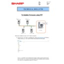
MX-3050N MX-3060N MX-3070N MX-3550N MX-3560N MX-3570N MX-4050N MX-4060N MX-4070N (serv.man36)
How to update firmware via FTP
FAQ
|
2
|
650.37 KB
|
|
|
MX-3050N MX-3060N MX-3070N MX-3550N MX-3560N MX-3570N MX-4050N MX-4060N MX-4070N (serv.man37)
Updated EEPROM Programming Procedure
FAQ
|
4
|
592.71 KB
|

|
MX-3050N MX-3060N MX-3070N MX-3550N MX-3560N MX-3570N MX-4050N MX-4060N MX-4070N (serv.man38)
MX3050-MX4070 Pantone LUT, How to Guide and application Support files. For use with Sharp Driver
FAQ
|
|
26.31 MB
|
|
|
MX-3050N MX-3060N MX-3070N MX-3550N MX-3560N MX-3570N MX-4050N MX-4060N MX-4070N (serv.man39)
Procedure to reset the Admin or Service Password. Please download relevant Request to reset Form below
FAQ
|
5
|
311.14 KB
|
|
|
MX-3050N MX-3060N MX-3070N MX-3550N MX-3560N MX-3570N MX-4050N MX-4060N MX-4070N (serv.man40)
Request to Reset Service Password Form Please fill in all sections of this form
FAQ
|
1
|
147.81 KB
|
|
|
MX-3050N MX-3060N MX-3070N MX-3550N MX-3560N MX-3570N MX-4050N MX-4060N MX-4070N (serv.man41)
Request to Reset Admin Password Form Please fill in all sections of this form
FAQ
|
1
|
147.88 KB
|

|
MX-3050N MX-3060N MX-3070N MX-3550N MX-3560N MX-3570N MX-4050N MX-4060N MX-4070N (serv.man228)
MSDS for Phoenix and Griffin Toner and Developer. Zipped file containing all.
Regulatory Data
|
|
933.93 KB
|

