|
|
MX-2640N MX-2640NR MX-2640FN MX-3140N MX-3140NR MX-3140FN MX-3640N MX-3640NR MX-3640FN (serv.man9)
Service Manual Revised June 2014.
Service Manual
|
127
|
65.06 MB
|
|
|
MX-2640N MX-2640NR MX-2640FN MX-3140N MX-3140NR MX-3140FN MX-3640N MX-3640NR MX-3640FN (serv.man10)
Installation Manual Revised June 2014.
Service Manual
|
126
|
42.66 MB
|
|
|
MX-2640N MX-2640NR MX-2640FN MX-3140N MX-3140NR MX-3140FN MX-3640N MX-3640NR MX-3640FN (serv.man11)
MX2640N-MX3140N-MX3640N Circuit Diagram
Service Manual
|
127
|
17.76 MB
|
|
|
MX-2640N MX-2640NR MX-2640FN MX-3140N MX-3140NR MX-3140FN MX-3640N MX-3640NR MX-3640FN (serv.man37)
Installation Manual Revised June 2014.
Service Manual
|
126
|
42.66 MB
|
|
|
MX-2640N MX-2640NR MX-2640FN MX-3140N MX-3140NR MX-3140FN MX-3640N MX-3640NR MX-3640FN (serv.man38)
MX2640N-MX3140N-MX3640N Circuit Diagram
Service Manual
|
127
|
17.76 MB
|

|
MX-2640N MX-2640NR MX-2640FN MX-3140N MX-3140NR MX-3140FN MX-3640N MX-3640NR MX-3640FN (serv.man14)
HTML version of Operator Manual.
User Manual / Operation Manual
|
|
34.75 MB
|
|
|
MX-2640N MX-2640NR MX-2640FN MX-3140N MX-3140NR MX-3140FN MX-3640N MX-3640NR MX-3640FN (serv.man15)
PDF version of Operator Manual.
User Manual / Operation Manual
|
127
|
12.99 MB
|

|
MX-2640N MX-2640NR MX-2640FN MX-3140N MX-3140NR MX-3140FN MX-3640N MX-3640NR MX-3640FN (serv.man16)
File 001
User Manual / Operation Manual
|
|
82.77 MB
|

|
MX-2640N MX-2640NR MX-2640FN MX-3140N MX-3140NR MX-3140FN MX-3640N MX-3640NR MX-3640FN (serv.man17)
File 002
User Manual / Operation Manual
|
|
84.09 MB
|

|
MX-2640N MX-2640NR MX-2640FN MX-3140N MX-3140NR MX-3140FN MX-3640N MX-3640NR MX-3640FN (serv.man18)
File 003
User Manual / Operation Manual
|
|
94.66 MB
|

|
MX-2640N MX-2640NR MX-2640FN MX-3140N MX-3140NR MX-3140FN MX-3640N MX-3640NR MX-3640FN (serv.man19)
File 004
User Manual / Operation Manual
|
|
94.64 MB
|

|
MX-2640N MX-2640NR MX-2640FN MX-3140N MX-3140NR MX-3140FN MX-3640N MX-3640NR MX-3640FN (serv.man20)
File 005
User Manual / Operation Manual
|
|
94.66 MB
|

|
MX-2640N MX-2640NR MX-2640FN MX-3140N MX-3140NR MX-3140FN MX-3640N MX-3640NR MX-3640FN (serv.man21)
File 006
User Manual / Operation Manual
|
|
94.58 MB
|

|
MX-2640N MX-2640NR MX-2640FN MX-3140N MX-3140NR MX-3140FN MX-3640N MX-3640NR MX-3640FN (serv.man22)
File 007
User Manual / Operation Manual
|
|
94.66 MB
|

|
MX-2640N MX-2640NR MX-2640FN MX-3140N MX-3140NR MX-3140FN MX-3640N MX-3640NR MX-3640FN (serv.man23)
File 008
User Manual / Operation Manual
|
|
94.62 MB
|

|
MX-2640N MX-2640NR MX-2640FN MX-3140N MX-3140NR MX-3140FN MX-3640N MX-3640NR MX-3640FN (serv.man24)
File 009
User Manual / Operation Manual
|
|
94.58 MB
|

|
MX-2640N MX-2640NR MX-2640FN MX-3140N MX-3140NR MX-3140FN MX-3640N MX-3640NR MX-3640FN (serv.man25)
File 010
User Manual / Operation Manual
|
|
94.61 MB
|

|
MX-2640N MX-2640NR MX-2640FN MX-3140N MX-3140NR MX-3140FN MX-3640N MX-3640NR MX-3640FN (serv.man26)
File 011 Restoration File
User Manual / Operation Manual
|
|
61.88 MB
|

|
MX-2640N MX-2640NR MX-2640FN MX-3140N MX-3140NR MX-3140FN MX-3640N MX-3640NR MX-3640FN (serv.man41)
HTML version of Operator Manual.
User Manual / Operation Manual
|
|
34.75 MB
|
|
|
MX-2640N MX-2640NR MX-2640FN MX-3140N MX-3140NR MX-3140FN MX-3640N MX-3640NR MX-3640FN (serv.man42)
PDF version of Operator Manual.
User Manual / Operation Manual
|
127
|
12.99 MB
|

|
MX-2640N MX-2640NR MX-2640FN MX-3140N MX-3140NR MX-3140FN MX-3640N MX-3640NR MX-3640FN (serv.man43)
File 001
User Manual / Operation Manual
|
|
82.77 MB
|

|
MX-2640N MX-2640NR MX-2640FN MX-3140N MX-3140NR MX-3140FN MX-3640N MX-3640NR MX-3640FN (serv.man44)
File 002
User Manual / Operation Manual
|
|
84.09 MB
|

|
MX-2640N MX-2640NR MX-2640FN MX-3140N MX-3140NR MX-3140FN MX-3640N MX-3640NR MX-3640FN (serv.man45)
File 003
User Manual / Operation Manual
|
|
94.66 MB
|

|
MX-2640N MX-2640NR MX-2640FN MX-3140N MX-3140NR MX-3140FN MX-3640N MX-3640NR MX-3640FN (serv.man46)
File 004
User Manual / Operation Manual
|
|
94.64 MB
|

|
MX-2640N MX-2640NR MX-2640FN MX-3140N MX-3140NR MX-3140FN MX-3640N MX-3640NR MX-3640FN (serv.man47)
File 005
User Manual / Operation Manual
|
|
94.66 MB
|

|
MX-2640N MX-2640NR MX-2640FN MX-3140N MX-3140NR MX-3140FN MX-3640N MX-3640NR MX-3640FN (serv.man48)
File 006
User Manual / Operation Manual
|
|
94.58 MB
|

|
MX-2640N MX-2640NR MX-2640FN MX-3140N MX-3140NR MX-3140FN MX-3640N MX-3640NR MX-3640FN (serv.man49)
File 007
User Manual / Operation Manual
|
|
94.66 MB
|

|
MX-2640N MX-2640NR MX-2640FN MX-3140N MX-3140NR MX-3140FN MX-3640N MX-3640NR MX-3640FN (serv.man50)
File 008
User Manual / Operation Manual
|
|
94.62 MB
|

|
MX-2640N MX-2640NR MX-2640FN MX-3140N MX-3140NR MX-3140FN MX-3640N MX-3640NR MX-3640FN (serv.man51)
File 009
User Manual / Operation Manual
|
|
94.58 MB
|

|
MX-2640N MX-2640NR MX-2640FN MX-3140N MX-3140NR MX-3140FN MX-3640N MX-3640NR MX-3640FN (serv.man52)
File 010
User Manual / Operation Manual
|
|
94.61 MB
|

|
MX-2640N MX-2640NR MX-2640FN MX-3140N MX-3140NR MX-3140FN MX-3640N MX-3640NR MX-3640FN (serv.man53)
File 011 Restoration File
User Manual / Operation Manual
|
|
61.88 MB
|
|
|
MX-2640N MX-2640NR MX-2640FN MX-3140N MX-3140NR MX-3140FN MX-3640N MX-3640NR MX-3640FN (serv.man12)
Parts Guide (Revised May 2017).
Service Manual / Parts Guide
|
127
|
42.71 MB
|
|
|
MX-2640N MX-2640NR MX-2640FN MX-3140N MX-3140NR MX-3140FN MX-3640N MX-3640NR MX-3640FN (serv.man13)
Pwb Component Parts Guide - February 2013
Service Manual / Parts Guide
|
47
|
413.36 KB
|
|
|
MX-2640N MX-2640NR MX-2640FN MX-3140N MX-3140NR MX-3140FN MX-3640N MX-3640NR MX-3640FN (serv.man39)
Parts Guide (Revised May 2017).
Service Manual / Parts Guide
|
127
|
42.71 MB
|
|
|
MX-2640N MX-2640NR MX-2640FN MX-3140N MX-3140NR MX-3140FN MX-3640N MX-3640NR MX-3640FN (serv.man40)
Pwb Component Parts Guide - February 2013
Service Manual / Parts Guide
|
47
|
413.36 KB
|
|
|
MX-2640N MX-2640NR MX-2640FN MX-3140N MX-3140NR MX-3140FN MX-3640N MX-3640NR MX-3640FN (serv.man6)
CCE-1730 Change of harness
Service Manual / Specification
|
2
|
197.74 KB
|
|
|
MX-2640N MX-2640NR MX-2640FN MX-3140N MX-3140NR MX-3140FN MX-3640N MX-3640NR MX-3640FN (serv.man7)
CHANGE OF SPF HINGE
Service Manual / Specification
|
2
|
575.03 KB
|
|
|
MX-2640N MX-2640NR MX-2640FN MX-3140N MX-3140NR MX-3140FN MX-3640N MX-3640NR MX-3640FN (serv.man8)
Improvement of noise from paper feed reverse roller
Service Manual / Specification
|
2
|
316.2 KB
|
|
|
MX-2640N MX-2640NR MX-2640FN MX-3140N MX-3140NR MX-3140FN MX-3640N MX-3640NR MX-3640FN (serv.man33)
CCE-1730 Change of harness
Service Manual / Specification
|
2
|
197.74 KB
|
|
|
MX-2640N MX-2640NR MX-2640FN MX-3140N MX-3140NR MX-3140FN MX-3640N MX-3640NR MX-3640FN (serv.man34)
CHANGE OF SPF HINGE
Service Manual / Specification
|
2
|
575.03 KB
|
|
|
MX-2640N MX-2640NR MX-2640FN MX-3140N MX-3140NR MX-3140FN MX-3640N MX-3640NR MX-3640FN (serv.man35)
Improvement of noise from paper feed reverse roller
Service Manual / Specification
|
2
|
316.2 KB
|
|
|
MX-2640N MX-2640NR MX-2640FN MX-3140N MX-3140NR MX-3140FN MX-3640N MX-3640NR MX-3640FN (serv.man67)
Change of operation panel unit for common use with other models.
Service Manual / Technical Bulletin
|
2
|
202.83 KB
|
|
|
MX-2640N MX-2640NR MX-2640FN MX-3140N MX-3140NR MX-3140FN MX-3640N MX-3640NR MX-3640FN (serv.man68)
Parts change for productivity improvement.
Service Manual / Technical Bulletin
|
3
|
184.15 KB
|
|
|
MX-2640N MX-2640NR MX-2640FN MX-3140N MX-3140NR MX-3140FN MX-3640N MX-3640NR MX-3640FN (serv.man69)
CCE 1785 DISCONTINUATION OF SUPPLY OF LAMP BASE
Service Manual / Technical Bulletin
|
4
|
400.71 KB
|
|
|
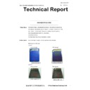
MX-2640N MX-2640NR MX-2640FN MX-3140N MX-3140NR MX-3140FN MX-3640N MX-3640NR MX-3640FN (serv.man70)
CHANGE OF SD CARD
Service Manual / Technical Bulletin
|
3
|
287.22 KB
|
|
|
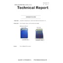
MX-2640N MX-2640NR MX-2640FN MX-3140N MX-3140NR MX-3140FN MX-3640N MX-3640NR MX-3640FN (serv.man71)
Change of SD card
Service Manual / Technical Bulletin
|
2
|
165.68 KB
|
|
|
MX-2640N MX-2640NR MX-2640FN MX-3140N MX-3140NR MX-3140FN MX-3640N MX-3640NR MX-3640FN (serv.man72)
Change of Ops panel
Service Manual / Technical Bulletin
|
2
|
440.88 KB
|
|
|
MX-2640N MX-2640NR MX-2640FN MX-3140N MX-3140NR MX-3140FN MX-3640N MX-3640NR MX-3640FN (serv.man73)
Change of TN filter.
Service Manual / Technical Bulletin
|
2
|
132.03 KB
|
|
|
MX-2640N MX-2640NR MX-2640FN MX-3140N MX-3140NR MX-3140FN MX-3640N MX-3640NR MX-3640FN (serv.man74)
Removal of handle support holder handle support plate
Service Manual / Technical Bulletin
|
2
|
323.21 KB
|
|
|
MX-2640N MX-2640NR MX-2640FN MX-3140N MX-3140NR MX-3140FN MX-3640N MX-3640NR MX-3640FN (serv.man75)
Change of sensor for RSPF unit
Service Manual / Technical Bulletin
|
3
|
750.85 KB
|
|
|
MX-2640N MX-2640NR MX-2640FN MX-3140N MX-3140NR MX-3140FN MX-3640N MX-3640NR MX-3640FN (serv.man76)
CHANGE OF SPF HINGE
Service Manual / Technical Bulletin
|
2
|
575.03 KB
|
|
|
MX-2640N MX-2640NR MX-2640FN MX-3140N MX-3140NR MX-3140FN MX-3640N MX-3640NR MX-3640FN (serv.man77)
CCE 1645 CHANGE OF TRANSPORT FOLLOWER ROLLER
Service Manual / Technical Bulletin
|
2
|
179.18 KB
|
|
|
MX-2640N MX-2640NR MX-2640FN MX-3140N MX-3140NR MX-3140FN MX-3640N MX-3640NR MX-3640FN (serv.man78)
CCE 1620 CHANGE IN SHAPE OF DISCHARGE BRUSH
Service Manual / Technical Bulletin
|
2
|
113.81 KB
|
|
|
MX-2640N MX-2640NR MX-2640FN MX-3140N MX-3140NR MX-3140FN MX-3640N MX-3640NR MX-3640FN (serv.man79)
Change in material for winder pulley on optical baseplate unit (Correction).
Service Manual / Technical Bulletin
|
8
|
964.61 KB
|
|
|
MX-2640N MX-2640NR MX-2640FN MX-3140N MX-3140NR MX-3140FN MX-3640N MX-3640NR MX-3640FN (serv.man80)
CCE-1554- MODIFICATION OF WIRING FOR MSW LOWER HARNESS AND POWER SUPPLY HARNESS
Service Manual / Technical Bulletin
|
3
|
747.22 KB
|
|
|
MX-2640N MX-2640NR MX-2640FN MX-3140N MX-3140NR MX-3140FN MX-3640N MX-3640NR MX-3640FN (serv.man81)
CCE-1589 Registration of hinge plate as service part
Service Manual / Technical Bulletin
|
3
|
511.65 KB
|
|
|
MX-2640N MX-2640NR MX-2640FN MX-3140N MX-3140NR MX-3140FN MX-3640N MX-3640NR MX-3640FN (serv.man82)
Service parts setup (Pipe upper cover unit).
Service Manual / Technical Bulletin
|
2
|
34.06 KB
|
|
|
MX-2640N MX-2640NR MX-2640FN MX-3140N MX-3140NR MX-3140FN MX-3640N MX-3640NR MX-3640FN (serv.man83)
Rom Upgrade (12 - (13). See also Technical Bulletin CCE1563R. Firmware uploaded on 15 04 16.
Service Manual / Technical Bulletin
|
3
|
33.85 KB
|
|
|
MX-2640N MX-2640NR MX-2640FN MX-3140N MX-3140NR MX-3140FN MX-3640N MX-3640NR MX-3640FN (serv.man84)
Notification of CPO (License Manager) and support for SHA-2.
Service Manual / Technical Bulletin
|
3
|
38.6 KB
|
|
|
MX-2640N MX-2640NR MX-2640FN MX-3140N MX-3140NR MX-3140FN MX-3640N MX-3640NR MX-3640FN (serv.man85)
CCE 1549 COUNTERMEASURE FOR NOISE FROM RSPF
Service Manual / Technical Bulletin
|
2
|
235.86 KB
|
|
|
MX-2640N MX-2640NR MX-2640FN MX-3140N MX-3140NR MX-3140FN MX-3640N MX-3640NR MX-3640FN (serv.man86)
Design change of upper cover.
Service Manual / Technical Bulletin
|
2
|
108.97 KB
|
|
|
MX-2640N MX-2640NR MX-2640FN MX-3140N MX-3140NR MX-3140FN MX-3640N MX-3640NR MX-3640FN (serv.man87)
CCE 1557 CHANGE OF SILENCE MOQUETTE ON RSPF
Service Manual / Technical Bulletin
|
2
|
203.99 KB
|
|
|
MX-2640N MX-2640NR MX-2640FN MX-3140N MX-3140NR MX-3140FN MX-3640N MX-3640NR MX-3640FN (serv.man88)
Change in shape of open close lock pawl.
Service Manual / Technical Bulletin
|
3
|
97.28 KB
|
|
|
MX-2640N MX-2640NR MX-2640FN MX-3140N MX-3140NR MX-3140FN MX-3640N MX-3640NR MX-3640FN (serv.man89)
Change of material in winder pulley on optical base plate unit.
Service Manual / Technical Bulletin
|
8
|
955.17 KB
|
|
|
MX-2640N MX-2640NR MX-2640FN MX-3140N MX-3140NR MX-3140FN MX-3640N MX-3640NR MX-3640FN (serv.man90)
Change in shape of tension plate R for DSPF RSPF.
Service Manual / Technical Bulletin
|
3
|
217.95 KB
|
|
|
MX-2640N MX-2640NR MX-2640FN MX-3140N MX-3140NR MX-3140FN MX-3640N MX-3640NR MX-3640FN (serv.man91)
Improvement for meandering of fuser belt.
Service Manual / Technical Bulletin
|
2
|
118.11 KB
|
|
|
MX-2640N MX-2640NR MX-2640FN MX-3140N MX-3140NR MX-3140FN MX-3640N MX-3640NR MX-3640FN (serv.man92)
Starting Powder List (This list takes priority over information in Service Manuals).
Service Manual / Technical Bulletin
|
4
|
66.25 KB
|
|
|
MX-2640N MX-2640NR MX-2640FN MX-3140N MX-3140NR MX-3140FN MX-3640N MX-3640NR MX-3640FN (serv.man93)
CAUTION ILLUSTRATIONS ADDED TO PACKING BOX.
Service Manual / Technical Bulletin
|
1
|
83.72 KB
|
|
|
MX-2640N MX-2640NR MX-2640FN MX-3140N MX-3140NR MX-3140FN MX-3640N MX-3640NR MX-3640FN (serv.man94)
CHANGE OF CONNECTION PLATE FOR IMPROVEMENT OF INSTALLATION OF LARGE CAPACITY DESK
Service Manual / Technical Bulletin
|
3
|
356.27 KB
|
|
|
MX-2640N MX-2640NR MX-2640FN MX-3140N MX-3140NR MX-3140FN MX-3640N MX-3640NR MX-3640FN (serv.man95)
COUNTERMEASURE FOR C4-00 OR L4-06 DUE TO JOINT FAILURE OF CLUTCH
Service Manual / Technical Bulletin
|
4
|
334.29 KB
|
|
|
MX-2640N MX-2640NR MX-2640FN MX-3140N MX-3140NR MX-3140FN MX-3640N MX-3640NR MX-3640FN (serv.man96)
Not Booting Up Blank Screen Procedure
Service Manual / Technical Bulletin
|
2
|
577.88 KB
|
|
|
MX-2640N MX-2640NR MX-2640FN MX-3140N MX-3140NR MX-3140FN MX-3640N MX-3640NR MX-3640FN (serv.man97)
CCE-1309 REVISED BULLETIN FOR PHOTO SENSOR TROUBLE PLEASE READ NOTES MARKED IN RED FOR PART NUMBER CHANGES IN THIS BULLETIN
Service Manual / Technical Bulletin
|
5
|
632.99 KB
|
|
|
MX-2640N MX-2640NR MX-2640FN MX-3140N MX-3140NR MX-3140FN MX-3640N MX-3640NR MX-3640FN (serv.man98)
CCE 1416R REMOVAL OF LSU SHUTTER
Service Manual / Technical Bulletin
|
2
|
157.53 KB
|
|
|
MX-2640N MX-2640NR MX-2640FN MX-3140N MX-3140NR MX-3140FN MX-3640N MX-3640NR MX-3640FN (serv.man99)
CCE 1466 RSPF ORIGINAL DETECT ACTUATOR STRENGTH IMPROVEMENT
Service Manual / Technical Bulletin
|
2
|
219.74 KB
|
|
|
MX-2640N MX-2640NR MX-2640FN MX-3140N MX-3140NR MX-3140FN MX-3640N MX-3640NR MX-3640FN (serv.man100)
CCE 1460 CHANGE IN COLOR OF BELT COUPLING JOINT
Service Manual / Technical Bulletin
|
2
|
169.78 KB
|
|
|
MX-2640N MX-2640NR MX-2640FN MX-3140N MX-3140NR MX-3140FN MX-3640N MX-3640NR MX-3640FN (serv.man101)
Material change Rotation Plate Sheet.
Service Manual / Technical Bulletin
|
3
|
290.1 KB
|
|
|
MX-2640N MX-2640NR MX-2640FN MX-3140N MX-3140NR MX-3140FN MX-3640N MX-3640NR MX-3640FN (serv.man102)
CCE 1446 COUNTERMEASURE FOR NOISE FROM RIGHT LOWER DOOR UNIT, RIGHT DOOR UNIT AND MF PAPER FEED UNIT
Service Manual / Technical Bulletin
|
6
|
549.83 KB
|
|
|
MX-2640N MX-2640NR MX-2640FN MX-3140N MX-3140NR MX-3140FN MX-3640N MX-3640NR MX-3640FN (serv.man103)
CCE 1399R2 IMPROVEMENT OF CONDUCTIVITY LEVEL BETWEEN FUSING UPPER STAY AND FUSING REAR DISCHARGE BRUSH
Service Manual / Technical Bulletin
|
4
|
351.75 KB
|
|
|
MX-2640N MX-2640NR MX-2640FN MX-3140N MX-3140NR MX-3140FN MX-3640N MX-3640NR MX-3640FN (serv.man104)
CCE 1389R COUNTERMEASURE FOR E7-11 TROUBLE
Service Manual / Technical Bulletin
|
3
|
278.04 KB
|
|
|
MX-2640N MX-2640NR MX-2640FN MX-3140N MX-3140NR MX-3140FN MX-3640N MX-3640NR MX-3640FN (serv.man105)
CCE 1439 NEWLY-REGISTERED SERVICE PARTS TO MODIFY PAPER JAM AND PAPER ALIGNMENT PROBLEM OCCURRED WHILE DISCHARGING PAPERS TO CENTER TRAY
Service Manual / Technical Bulletin
|
4
|
401.57 KB
|
|
|
MX-2640N MX-2640NR MX-2640FN MX-3140N MX-3140NR MX-3140FN MX-3640N MX-3640NR MX-3640FN (serv.man106)
CCE 1447 MEASURE AGAINST NOISE FROM REAR SIDE OF RIGHT LOWER DOOR UNIT
Service Manual / Technical Bulletin
|
1
|
70.19 KB
|
|
|
MX-2640N MX-2640NR MX-2640FN MX-3140N MX-3140NR MX-3140FN MX-3640N MX-3640NR MX-3640FN (serv.man107)
CCE 1448 COUNTERMEASURE FOR NOISE BY CLEARANCEOF JOINT SECTION BETWEEN DRIVE GEAR AND PARALLEL PIN
Service Manual / Technical Bulletin
|
1
|
84.31 KB
|
|
|
MX-2640N MX-2640NR MX-2640FN MX-3140N MX-3140NR MX-3140FN MX-3640N MX-3640NR MX-3640FN (serv.man108)
CCE 1433 STRENGTH ENHANCEMENT FOR CRACKING OF SOCKET FOR HINGE R ON UPPER CABINET REAR
Service Manual / Technical Bulletin
|
2
|
218.57 KB
|
|
|
MX-2640N MX-2640NR MX-2640FN MX-3140N MX-3140NR MX-3140FN MX-3640N MX-3640NR MX-3640FN (serv.man109)
Recommended shutdown procedure and Power Cycling of MFD
Service Manual / Technical Bulletin
|
1
|
186.43 KB
|
|
|
MX-2640N MX-2640NR MX-2640FN MX-3140N MX-3140NR MX-3140FN MX-3640N MX-3640NR MX-3640FN (serv.man110)
IMPORTANT Handling of EEPROM's.
Service Manual / Technical Bulletin
|
5
|
203.32 KB
|
|
|
MX-2640N MX-2640NR MX-2640FN MX-3140N MX-3140NR MX-3140FN MX-3640N MX-3640NR MX-3640FN (serv.man111)
CCE-1425 MODIFICATION OF TROUBLE CODE C1-10 or C1-14 DUE TO DEFECTIVE MC PWB
Service Manual / Technical Bulletin
|
2
|
218.6 KB
|
|
|
MX-2640N MX-2640NR MX-2640FN MX-3140N MX-3140NR MX-3140FN MX-3640N MX-3640NR MX-3640FN (serv.man112)
CCE-1420 DSK ROM UPGRADE MX-FR41U ONLY ICUM 0500Ad Bulletin Only
Service Manual / Technical Bulletin
|
3
|
118.84 KB
|
|
|
MX-2640N MX-2640NR MX-2640FN MX-3140N MX-3140NR MX-3140FN MX-3640N MX-3640NR MX-3640FN (serv.man113)
CCE-1399R IMPROVEMENT OF CONDUCTIVITY LEVEL BETWEEN FUSING UPPER STAY AND FUSING REAR DISCHARGE BRUSH
Service Manual / Technical Bulletin
|
4
|
351.08 KB
|
|
|
MX-2640N MX-2640NR MX-2640FN MX-3140N MX-3140NR MX-3140FN MX-3640N MX-3640NR MX-3640FN (serv.man114)
CCE 1410 FULL DETECT ERROR DUE TO FULL DETECT LEVER COMING OFF
Service Manual / Technical Bulletin
|
2
|
267.47 KB
|
|
|
MX-2640N MX-2640NR MX-2640FN MX-3140N MX-3140NR MX-3140FN MX-3640N MX-3640NR MX-3640FN (serv.man115)
CCE 1409 REMEDY FOR NOISE FROM READING FRONT REAR ROLLER AND PS CLUTCH
Service Manual / Technical Bulletin
|
3
|
282.54 KB
|
|
|
MX-2640N MX-2640NR MX-2640FN MX-3140N MX-3140NR MX-3140FN MX-3640N MX-3640NR MX-3640FN (serv.man116)
CCE 1408 CHANGE OF MANUFACTURER OF 2ND TRANSFER ROLLER FOR PRODUCTIVITY IMPROVEMENT
Service Manual / Technical Bulletin
|
2
|
161.78 KB
|
|
|
MX-2640N MX-2640NR MX-2640FN MX-3140N MX-3140NR MX-3140FN MX-3640N MX-3640NR MX-3640FN (serv.man117)
CCE 1404 ROM UPGRADE (11). V05.00.A2 Bulletin Only
Service Manual / Technical Bulletin
|
3
|
140.58 KB
|
|
|
MX-2640N MX-2640NR MX-2640FN MX-3140N MX-3140NR MX-3140FN MX-3640N MX-3640NR MX-3640FN (serv.man118)
Change in material of pick up roller.
Service Manual / Technical Bulletin
|
2
|
77.2 KB
|
|
|
MX-2640N MX-2640NR MX-2640FN MX-3140N MX-3140NR MX-3140FN MX-3640N MX-3640NR MX-3640FN (serv.man119)
CCE 1401 REMEDY FOR COLOR TONE CHANGE
Service Manual / Technical Bulletin
|
2
|
164.52 KB
|
|
|
MX-2640N MX-2640NR MX-2640FN MX-3140N MX-3140NR MX-3140FN MX-3640N MX-3640NR MX-3640FN (serv.man120)
CCE 1373 CHANGE OF WIRE LENGTH OF PAPER FEED HARNESS
Service Manual / Technical Bulletin
|
3
|
311.65 KB
|
|
|
MX-2640N MX-2640NR MX-2640FN MX-3140N MX-3140NR MX-3140FN MX-3640N MX-3640NR MX-3640FN (serv.man121)
CCE 1399 IMPROVEMENT OF CONDUCTIVITY LEVEL BETWEEN FUSING UPPER STAY AND FUSING REAR DISCHARGE BRUSH
Service Manual / Technical Bulletin
|
3
|
239.93 KB
|
|
|
MX-2640N MX-2640NR MX-2640FN MX-3140N MX-3140NR MX-3140FN MX-3640N MX-3640NR MX-3640FN (serv.man122)
CCE 1394 ENHANCEMENT OF HOLDING SECTION ON FUSING REAR LOWER PAPER GUIDE TO PREVENT DAMAGE
Service Manual / Technical Bulletin
|
2
|
211.97 KB
|
|
|
MX-2640N MX-2640NR MX-2640FN MX-3140N MX-3140NR MX-3140FN MX-3640N MX-3640NR MX-3640FN (serv.man123)
Countermeasure for E7-11 trouble.
Service Manual / Technical Bulletin
|
3
|
125.27 KB
|
|
|
MX-2640N MX-2640NR MX-2640FN MX-3140N MX-3140NR MX-3140FN MX-3640N MX-3640NR MX-3640FN (serv.man124)
CCE 1380 REMOVAL OF ONE WAY GEAR AND GEAR 19T 35T
Service Manual / Technical Bulletin
|
2
|
212.56 KB
|
|
|
MX-2640N MX-2640NR MX-2640FN MX-3140N MX-3140NR MX-3140FN MX-3640N MX-3640NR MX-3640FN (serv.man125)
CCE 1367 ENHANCEMENT TO PREVENT C4-00 ERROR
Service Manual / Technical Bulletin
|
2
|
178.27 KB
|
|
|
MX-2640N MX-2640NR MX-2640FN MX-3140N MX-3140NR MX-3140FN MX-3640N MX-3640NR MX-3640FN (serv.man126)
ENHANCEMENT FOR DAMAGE OF FUSING BELT.
Service Manual / Technical Bulletin
|
2
|
210.36 KB
|
|
|
MX-2640N MX-2640NR MX-2640FN MX-3140N MX-3140NR MX-3140FN MX-3640N MX-3640NR MX-3640FN (serv.man127)
CCE 1386 CHANGE OF ASIC IN PCU PWB
Service Manual / Technical Bulletin
|
3
|
251.42 KB
|
|
|
MX-2640N MX-2640NR MX-2640FN MX-3140N MX-3140NR MX-3140FN MX-3640N MX-3640NR MX-3640FN (serv.man128)
CCE 1385 CHANGE OF LENS UNIT ETC. ASSOCIATED WITH CHANGE OF CCD ELEMENT
Service Manual / Technical Bulletin
|
3
|
279.04 KB
|
|
|
MX-2640N MX-2640NR MX-2640FN MX-3140N MX-3140NR MX-3140FN MX-3640N MX-3640NR MX-3640FN (serv.man129)
CCE 1383 REMEDY FOR NOISE FROM PS CLUTCH IN RSPF
Service Manual / Technical Bulletin
|
3
|
228.13 KB
|
|
|
MX-2640N MX-2640NR MX-2640FN MX-3140N MX-3140NR MX-3140FN MX-3640N MX-3640NR MX-3640FN (serv.man130)
CCE 1381 CHANGE IN SHAPE OF CAM SHAFT AND REMOVAL OF E RING
Service Manual / Technical Bulletin
|
2
|
150.49 KB
|
|
|
MX-2640N MX-2640NR MX-2640FN MX-3140N MX-3140NR MX-3140FN MX-3640N MX-3640NR MX-3640FN (serv.man131)
CCE 1375 CONFIRMATION OF DRIVER PWB AT THE TIME OF C1-14 TROUBLE
Service Manual / Technical Bulletin
|
2
|
186.97 KB
|
|
|
MX-2640N MX-2640NR MX-2640FN MX-3140N MX-3140NR MX-3140FN MX-3640N MX-3640NR MX-3640FN (serv.man132)
CCE1374 COUNTERMEASURE AGAINST ABRADED FUSING DRIVE GEAR
Service Manual / Technical Bulletin
|
3
|
264.21 KB
|
|
|
MX-2640N MX-2640NR MX-2640FN MX-3140N MX-3140NR MX-3140FN MX-3640N MX-3640NR MX-3640FN (serv.man133)
MATERIAL CHANGE WIDTH DETECT SENSOR FIXING PLATE.
Service Manual / Technical Bulletin
|
3
|
229.42 KB
|
|
|
MX-2640N MX-2640NR MX-2640FN MX-3140N MX-3140NR MX-3140FN MX-3640N MX-3640NR MX-3640FN (serv.man134)
CCE 1369 RON UPGRADE (6) DSK ONLY MXFR41U D01 ICU V 0402Ad Bulletin Only
Service Manual / Technical Bulletin
|
1
|
107.76 KB
|
|
|
MX-2640N MX-2640NR MX-2640FN MX-3140N MX-3140NR MX-3140FN MX-3640N MX-3640NR MX-3640FN (serv.man135)
CCE 1356 IMPROVEMENT TO PREVENT LOOSENED ROLL PIN INSERTED TO TRANSFER DRIVE ROLLER
Service Manual / Technical Bulletin
|
2
|
160.41 KB
|
|
|
MX-2640N MX-2640NR MX-2640FN MX-3140N MX-3140NR MX-3140FN MX-3640N MX-3640NR MX-3640FN (serv.man136)
CCE 1355 ENHANCEMENT OF 2ND TRANSFER BELT FRAME TO PREVENT BROKEN PAWL
Service Manual / Technical Bulletin
|
2
|
269.55 KB
|
|
|
MX-2640N MX-2640NR MX-2640FN MX-3140N MX-3140NR MX-3140FN MX-3640N MX-3640NR MX-3640FN (serv.man137)
CCE 1353 REMOVAL OF A FIXING SCREW MOUNTED TO DV SIDE PLATE ON DV UNIT
Service Manual / Technical Bulletin
|
2
|
125.72 KB
|
|
|
MX-2640N MX-2640NR MX-2640FN MX-3140N MX-3140NR MX-3140FN MX-3640N MX-3640NR MX-3640FN (serv.man138)
CCE 1319R Rom upgrade 9 additional information to CCE 1319
Service Manual / Technical Bulletin
|
3
|
155.66 KB
|
|
|
MX-2640N MX-2640NR MX-2640FN MX-3140N MX-3140NR MX-3140FN MX-3640N MX-3640NR MX-3640FN (serv.man139)
Countermeasures against noise from transport follower roller.
Service Manual / Technical Bulletin
|
5
|
1.13 MB
|
|
|
MX-2640N MX-2640NR MX-2640FN MX-3140N MX-3140NR MX-3140FN MX-3640N MX-3640NR MX-3640FN (serv.man140)
CCE 1334 NOTE WHEN INSTALLING MX-EB11 TO MX-2640N 3140N 3640N
Service Manual / Technical Bulletin
|
1
|
29.81 KB
|
|
|
MX-2640N MX-2640NR MX-2640FN MX-3140N MX-3140NR MX-3140FN MX-3640N MX-3640NR MX-3640FN (serv.man141)
Countermeasures against contamination of paper surface.
Service Manual / Technical Bulletin
|
2
|
24.64 KB
|
|
|
MX-2640N MX-2640NR MX-2640FN MX-3140N MX-3140NR MX-3140FN MX-3640N MX-3640NR MX-3640FN (serv.man142)
CCE 1354 Rom Upgrade (10)ICU V 04.02.A2 Bulletin Only
Service Manual / Technical Bulletin
|
2
|
125.89 KB
|
|
|
MX-2640N MX-2640NR MX-2640FN MX-3140N MX-3140NR MX-3140FN MX-3640N MX-3640NR MX-3640FN (serv.man143)
CCE 1347 COUNTERMEASURE FOR NOISE FROM FUSING DRIVE UNIT
Service Manual / Technical Bulletin
|
2
|
212.85 KB
|
|
|
MX-2640N MX-2640NR MX-2640FN MX-3140N MX-3140NR MX-3140FN MX-3640N MX-3640NR MX-3640FN (serv.man144)
CCE 1333R IMPROVEMENT OF NOISE FROM PAPER FEED REVERSE ROLLER
Service Manual / Technical Bulletin
|
2
|
194.71 KB
|
|
|
MX-2640N MX-2640NR MX-2640FN MX-3140N MX-3140NR MX-3140FN MX-3640N MX-3640NR MX-3640FN (serv.man145)
CHANGE OF HDD MANUFACTURER.
Service Manual / Technical Bulletin
|
2
|
152.37 KB
|
|
|
MX-2640N MX-2640NR MX-2640FN MX-3140N MX-3140NR MX-3140FN MX-3640N MX-3640NR MX-3640FN (serv.man146)
COUNTERMEASURE TO PREVENT DV BELT B FROM FALLING OFF RESULTING IN BLANK PAGES.
Service Manual / Technical Bulletin
|
2
|
148.65 KB
|
|
|
MX-2640N MX-2640NR MX-2640FN MX-3140N MX-3140NR MX-3140FN MX-3640N MX-3640NR MX-3640FN (serv.man147)
ENHANCEMENT FOR DAMAGE OF FUSING BELT
Service Manual / Technical Bulletin
|
2
|
67.71 KB
|
|
|
MX-2640N MX-2640NR MX-2640FN MX-3140N MX-3140NR MX-3140FN MX-3640N MX-3640NR MX-3640FN (serv.man148)
CCE 1329 Rom Upgrade (5) MX-FR41U DSK ONLY ICU V4.00.Ad Bulletin Only
Service Manual / Technical Bulletin
|
3
|
120.07 KB
|
|
|
MX-2640N MX-2640NR MX-2640FN MX-3140N MX-3140NR MX-3140FN MX-3640N MX-3640NR MX-3640FN (serv.man149)
CCE 1332 COUNTERMEASURE FOR NOISE FROM TRANSPORT FOLLOWER ROLLER
Service Manual / Technical Bulletin
|
5
|
819.33 KB
|
|
|
MX-2640N MX-2640NR MX-2640FN MX-3140N MX-3140NR MX-3140FN MX-3640N MX-3640NR MX-3640FN (serv.man150)
CCE-1319 ROM UPGRADE (9)ICUM ICU v0400A200 PCU v0403G200 SCU v0200A200 Bulletin Only
Service Manual / Technical Bulletin
|
3
|
139.04 KB
|
|
|
MX-2640N MX-2640NR MX-2640FN MX-3140N MX-3140NR MX-3140FN MX-3640N MX-3640NR MX-3640FN (serv.man151)
CCE-1321 ENHANCEMENT OF MF ROTATION PAWL SPRING
Service Manual / Technical Bulletin
|
2
|
127.18 KB
|
|
|
MX-2640N MX-2640NR MX-2640FN MX-3140N MX-3140NR MX-3140FN MX-3640N MX-3640NR MX-3640FN (serv.man152)
CCE-1315 MODIFICATION OF IMPROPER OPERATION OF THE COIN VENDOR WITH PARALLEL CONNECTION
Service Manual / Technical Bulletin
|
3
|
368.87 KB
|
|
|
MX-2640N MX-2640NR MX-2640FN MX-3140N MX-3140NR MX-3140FN MX-3640N MX-3640NR MX-3640FN (serv.man153)
CCE1303 MX-DE14, MX-DE16 MX-DE23 NEW REGISTRATION OF RIGHT DOOR UNIT AS SERVICE PARTS
Service Manual / Technical Bulletin
|
2
|
253.09 KB
|
|
|
MX-2640N MX-2640NR MX-2640FN MX-3140N MX-3140NR MX-3140FN MX-3640N MX-3640NR MX-3640FN (serv.man154)
CCE-1302 ENHANCEMENT OF COUNTERMEASURE FOR MEANDERING OF SECONDARY TRANSFER BELT
Service Manual / Technical Bulletin
|
2
|
154.63 KB
|
|
|
MX-2640N MX-2640NR MX-2640FN MX-3140N MX-3140NR MX-3140FN MX-3640N MX-3640NR MX-3640FN (serv.man155)
CCE-1285 ENHANCEMENT FOR L4-06 TROUBLE CODE
Service Manual / Technical Bulletin
|
3
|
334.86 KB
|
|
|
MX-2640N MX-2640NR MX-2640FN MX-3140N MX-3140NR MX-3140FN MX-3640N MX-3640NR MX-3640FN (serv.man156)
FIELD SUPPORT FOR MODIFICATION OF A NON-RESPONDING HOME KEY DUE TO STATIC ELECTRICITY.
Service Manual / Technical Bulletin
|
2
|
222.75 KB
|
|
|
MX-2640N MX-2640NR MX-2640FN MX-3140N MX-3140NR MX-3140FN MX-3640N MX-3640NR MX-3640FN (serv.man157)
Colour Registration Issues. Adjustments to overcome Misregistration.
Service Manual / Technical Bulletin
|
1
|
15.19 KB
|
|
|
MX-2640N MX-2640NR MX-2640FN MX-3140N MX-3140NR MX-3140FN MX-3640N MX-3640NR MX-3640FN (serv.man158)
CCE-1291 COUNTERMEASURE FOR NOISE FROM MF PAPER FEED UNIT
Service Manual / Technical Bulletin
|
2
|
137.74 KB
|
|
|
MX-2640N MX-2640NR MX-2640FN MX-3140N MX-3140NR MX-3140FN MX-3640N MX-3640NR MX-3640FN (serv.man159)
CCE-1257 1ST TRANSFER BELT CLEANING FAILURE DUE TO THE FLIPPED 1ST TRANSFER BLADE
Service Manual / Technical Bulletin
|
3
|
342.54 KB
|
|
|
MX-2640N MX-2640NR MX-2640FN MX-3140N MX-3140NR MX-3140FN MX-3640N MX-3640NR MX-3640FN (serv.man160)
CCE-1274 MX-FR41U Rom Upgrade V3 (Bulletin only)
Service Manual / Technical Bulletin
|
3
|
22.75 KB
|
|
|
MX-2640N MX-2640NR MX-2640FN MX-3140N MX-3140NR MX-3140FN MX-3640N MX-3640NR MX-3640FN (serv.man161)
CCE-1282 IMPROVEMENT OF PAPER FEEDING RELIABILITY OF BYPASS TRAY BY CHANGING THE SHAPE OF MF CAM COLLAR
Service Manual / Technical Bulletin
|
2
|
233.14 KB
|
|
|
MX-2640N MX-2640NR MX-2640FN MX-3140N MX-3140NR MX-3140FN MX-3640N MX-3640NR MX-3640FN (serv.man162)
CCE-1280 COUNTERMEASURE FOR NOISE FROM RSPF PAPER FEED SECTION REAR SIDE
Service Manual / Technical Bulletin
|
2
|
45.46 KB
|
|
|
MX-2640N MX-2640NR MX-2640FN MX-3140N MX-3140NR MX-3140FN MX-3640N MX-3640NR MX-3640FN (serv.man163)
REDUCING VIBRATION OF HDD AND CHANGE OF HDD DUE TO DISCONTINUATION OF PRODUCTION.
Service Manual / Technical Bulletin
|
4
|
1.22 MB
|
|
|
MX-2640N MX-2640NR MX-2640FN MX-3140N MX-3140NR MX-3140FN MX-3640N MX-3640NR MX-3640FN (serv.man164)
MODIFICATION OF CONTROL PWB FOR PRODUCTIVITY IMPROVEMENT.
Service Manual / Technical Bulletin
|
1
|
26.79 KB
|
|
|
MX-2640N MX-2640NR MX-2640FN MX-3140N MX-3140NR MX-3140FN MX-3640N MX-3640NR MX-3640FN (serv.man165)
REMEDY FOR SKIPPING OF COUPLING GEAR ON DRUM SHAFT UNIT
Service Manual / Technical Bulletin
|
1
|
29.05 KB
|
|
|
MX-2640N MX-2640NR MX-2640FN MX-3140N MX-3140NR MX-3140FN MX-3640N MX-3640NR MX-3640FN (serv.man166)
COUNTERMEASURE AGAINST NOISE FROM THE TRANSPORT FOLLOWER ROLLER IN RSPF BASE TRAY
Service Manual / Technical Bulletin
|
2
|
49.99 KB
|
|
|
MX-2640N MX-2640NR MX-2640FN MX-3140N MX-3140NR MX-3140FN MX-3640N MX-3640NR MX-3640FN (serv.man167)
CHANGE OF PHOTO SENSOR
Service Manual / Technical Bulletin
|
2
|
111.52 KB
|
|
|
MX-2640N MX-2640NR MX-2640FN MX-3140N MX-3140NR MX-3140FN MX-3640N MX-3640NR MX-3640FN (serv.man168)
Combined MFP Firmware Version ICUM BOOT MAIN03.00.A2.00 ICUM MAIN 03.00.A2.00- C00 Jan 14 - Bulletin Only
Service Manual / Technical Bulletin
|
3
|
26.65 KB
|
|
|
MX-2640N MX-2640NR MX-2640FN MX-3140N MX-3140NR MX-3140FN MX-3640N MX-3640NR MX-3640FN (serv.man169)
ELIMINATION OF LCD PROTECT MOLT OF 10.1 INCH OPERATION PANEL.
Service Manual / Technical Bulletin
|
2
|
180.25 KB
|
|
|
MX-2640N MX-2640NR MX-2640FN MX-3140N MX-3140NR MX-3140FN MX-3640N MX-3640NR MX-3640FN (serv.man170)
FIELD SUPPORT FOR REDUCTION OF FUSING PERFORMANCE AND WEB NOISE IN HIGH TEMPERATURE ENVIRONMENT
Service Manual / Technical Bulletin
|
3
|
166.39 KB
|
|
|
MX-2640N MX-2640NR MX-2640FN MX-3140N MX-3140NR MX-3140FN MX-3640N MX-3640NR MX-3640FN (serv.man171)
COUNTERMEASURE FOR VIBRATION NOISE DUE TO CONTAMINATION OF WEB
Service Manual / Technical Bulletin
|
2
|
156.87 KB
|
|
|
MX-2640N MX-2640NR MX-2640FN MX-3140N MX-3140NR MX-3140FN MX-3640N MX-3640NR MX-3640FN (serv.man172)
CLEANING TROUBLE OF 1ST TRANSFER BELT DUE TO FLIP OF PRIMARY TRANSFER BLADE
Service Manual / Technical Bulletin
|
6
|
416.47 KB
|
|
|
MX-2640N MX-2640NR MX-2640FN MX-3140N MX-3140NR MX-3140FN MX-3640N MX-3640NR MX-3640FN (serv.man173)
REMEDY FOR TONER DISPERSION FROM DV UNIT
Service Manual / Technical Bulletin
|
3
|
86.31 KB
|
|
|
MX-2640N MX-2640NR MX-2640FN MX-3140N MX-3140NR MX-3140FN MX-3640N MX-3640NR MX-3640FN (serv.man174)
ELIMINATION OF SEPARATE PLATE PROTECTPAWL FOR PRODUCTIVITY IMPROVEMENT
Service Manual / Technical Bulletin
|
1
|
65.65 KB
|
|
|
MX-2640N MX-2640NR MX-2640FN MX-3140N MX-3140NR MX-3140FN MX-3640N MX-3640NR MX-3640FN (serv.man175)
COUNTERMEASURE FOR NOISE FROM READING REAR ROLLER OF RSPF TRANSPORT SECTION
Service Manual / Technical Bulletin
|
2
|
70.86 KB
|
|
|
MX-2640N MX-2640NR MX-2640FN MX-3140N MX-3140NR MX-3140FN MX-3640N MX-3640NR MX-3640FN (serv.man176)
IMPROVEMENT OF STRENGTH FOR HINGE MOUNTING SECTION OF SPF BASE TRAY
Service Manual / Technical Bulletin
|
2
|
239.86 KB
|
|
|
MX-2640N MX-2640NR MX-2640FN MX-3140N MX-3140NR MX-3140FN MX-3640N MX-3640NR MX-3640FN (serv.man177)
COUNTERMEASURE FOR NOISE FROM MAIN DRIVE UNIT
Service Manual / Technical Bulletin
|
8
|
1.24 MB
|
|
|
MX-2640N MX-2640NR MX-2640FN MX-3140N MX-3140NR MX-3140FN MX-3640N MX-3640NR MX-3640FN (serv.man178)
CCE1195 ARIES2 DSK FR41U B01 ICU MAIN 02.11.Ad FIXES FOR E7-03 Paper empty BULLITEN ONLY
Service Manual / Technical Bulletin
|
1
|
17.28 KB
|
|
|
MX-2640N MX-2640NR MX-2640FN MX-3140N MX-3140NR MX-3140FN MX-3640N MX-3640NR MX-3640FN (serv.man179)
CHANGE OF FUSER FRONT AND REAR SEPERATION PLATE HOLDER
Service Manual / Technical Bulletin
|
2
|
84.57 KB
|
|
|
MX-2640N MX-2640NR MX-2640FN MX-3140N MX-3140NR MX-3140FN MX-3640N MX-3640NR MX-3640FN (serv.man180)
Combined MFP Firmware Version ICUM BOOT MAIN 02.10.A2 ICUM MAIN 02.10.A2- Production Run Sept 2013 Fix for E7-03 No output tray allowed - Bulletin Only
Service Manual / Technical Bulletin
|
2
|
19.18 KB
|
|
|
MX-2640N MX-2640NR MX-2640FN MX-3140N MX-3140NR MX-3140FN MX-3640N MX-3640NR MX-3640FN (serv.man181)
Enhancement of dust control for the scanner unit.
Service Manual / Technical Bulletin
|
2
|
61.05 KB
|
|
|
MX-2640N MX-2640NR MX-2640FN MX-3140N MX-3140NR MX-3140FN MX-3640N MX-3640NR MX-3640FN (serv.man182)
CHANGE OF HARNESS TIE FOR TOUCH PANEL HARNESS
Service Manual / Technical Bulletin
|
2
|
121.38 KB
|
|
|
MX-2640N MX-2640NR MX-2640FN MX-3140N MX-3140NR MX-3140FN MX-3640N MX-3640NR MX-3640FN (serv.man183)
PREVENTION OF PRIMARY TRANSFER BELT CLEANING BLADE FLIP
Service Manual / Technical Bulletin
|
6
|
419.47 KB
|
|
|
MX-2640N MX-2640NR MX-2640FN MX-3140N MX-3140NR MX-3140FN MX-3640N MX-3640NR MX-3640FN (serv.man184)
CCE1173 ARIES2 DSK FR41U B00 ICU MAIN 02.02.Ad FIXES FOR U2-42 E7-03 F6-00 E7-03 (BULLETIN ONLY)
Service Manual / Technical Bulletin
|
4
|
25.6 KB
|
|
|
MX-2640N MX-2640NR MX-2640FN MX-3140N MX-3140NR MX-3140FN MX-3640N MX-3640NR MX-3640FN (serv.man185)
Running Changes For MX-361FB Fusing Belt
Service Manual / Technical Bulletin
|
1
|
11.98 KB
|
|
|
MX-2640N MX-2640NR MX-2640FN MX-3140N MX-3140NR MX-3140FN MX-3640N MX-3640NR MX-3640FN (serv.man186)
For MAIN MACHINE AND MX-DE12 13 14 20 PAPER FEED UNIT CHANGES TO CREATE COMMON PARTS COMPATIBILITY WITH OTHER MODELS
Service Manual / Technical Bulletin
|
7
|
387.2 KB
|
|
|
MX-2640N MX-2640NR MX-2640FN MX-3140N MX-3140NR MX-3140FN MX-3640N MX-3640NR MX-3640FN (serv.man187)
ENHANCEMENT OF POD2 ACTUATOR DELIVERY LOWER PG TO PREVENT DETATCHMENT
Service Manual / Technical Bulletin
|
2
|
116.93 KB
|
|
|
MX-2640N MX-2640NR MX-2640FN MX-3140N MX-3140NR MX-3140FN MX-3640N MX-3640NR MX-3640FN (serv.man188)
Improvement for noise from RSPF DSPF transport section
Service Manual / Technical Bulletin
|
2
|
91.19 KB
|
|
|
MX-2640N MX-2640NR MX-2640FN MX-3140N MX-3140NR MX-3140FN MX-3640N MX-3640NR MX-3640FN (serv.man189)
Countermeasure for deviation of the hole punch position
Service Manual / Technical Bulletin
|
2
|
35.9 KB
|
|
|
MX-2640N MX-2640NR MX-2640FN MX-3140N MX-3140NR MX-3140FN MX-3640N MX-3640NR MX-3640FN (serv.man190)
MX2640N-MX3140N-MX3640N - Combined MFP Firmware Version 0120A200 ICUM 01200A200 ICU - Production Run A04 March 2013-Bulletin Only
Service Manual / Technical Bulletin
|
2
|
57.06 KB
|
|
|
MX-2640N MX-2640NR MX-2640FN MX-3140N MX-3140NR MX-3140FN MX-3640N MX-3640NR MX-3640FN (serv.man191)
IMPROVEMENT OF NOISE FROM PAPER FEED DRIVE UNIT SECTION
Service Manual / Technical Bulletin
|
2
|
133.11 KB
|
|
|
MX-2640N MX-2640NR MX-2640FN MX-3140N MX-3140NR MX-3140FN MX-3640N MX-3640NR MX-3640FN (serv.man192)
CCE-1112 -COUNTERMEASURE FOR DEVIATION OF PUNCH HOLE POSITION
Service Manual / Technical Bulletin
|
1
|
32.04 KB
|
|
|
MX-2640N MX-2640NR MX-2640FN MX-3140N MX-3140NR MX-3140FN MX-3640N MX-3640NR MX-3640FN (serv.man193)
CCE-1111 -WIRELESS LAN SET UP METHOD
Service Manual / Technical Bulletin
|
1
|
31.2 KB
|
|
|
MX-2640N MX-2640NR MX-2640FN MX-3140N MX-3140NR MX-3140FN MX-3640N MX-3640NR MX-3640FN (serv.man194)
MX2640N-MX3140N-MX3640N - Combined MFP Firmware Version 0101A200 ICUM 0100A200 ICU - Production Run A02 December 2012 - BULLETIN ONLY
Service Manual / Technical Bulletin
|
1
|
15.64 KB
|
|
|
MX-2640N MX-2640NR MX-2640FN MX-3140N MX-3140NR MX-3140FN MX-3640N MX-3640NR MX-3640FN (serv.man195)
NEWLY-CREATED MX-RB10N (PAPER PASS UNIT)
Service Manual / Technical Bulletin
|
2
|
74.07 KB
|
|
|
MX-2640N MX-2640NR MX-2640FN MX-3140N MX-3140NR MX-3140FN MX-3640N MX-3640NR MX-3640FN (serv.man196)
CHANGE OF SCREW FOR SCANNER HEATER KIT (DKIT-0427FC )(FOR MX-2640N 3140N 3640N)
Service Manual / Technical Bulletin
|
2
|
114.94 KB
|

|
MX-2640N MX-2640NR MX-2640FN MX-3140N MX-3140NR MX-3140FN MX-3640N MX-3640NR MX-3640FN (serv.man57)
Special firmware to support SMBv2 for scanning 06.00.A2.B0
Driver / Update
|
|
184.22 MB
|

|
MX-2640N MX-2640NR MX-2640FN MX-3140N MX-3140NR MX-3140FN MX-3640N MX-3640NR MX-3640FN (serv.man58)
Special DSK firmware to support SMBv2 for scanning 06.00.A2.B0. Only use this firmware on machines with DSK fitted
Driver / Update
|
|
184.57 MB
|

|
MX-2640N MX-2640NR MX-2640FN MX-3140N MX-3140NR MX-3140FN MX-3640N MX-3640NR MX-3640FN (serv.man59)
Special firmware for issue with print stops because customer selecting A3W. Version 06.00.A2.u0_B Please change Sim55-3 SW27-6 0 - 1
Driver / Update
|
|
184.21 MB
|

|
MX-2640N MX-2640NR MX-2640FN MX-3140N MX-3140NR MX-3140FN MX-3640N MX-3640NR MX-3640FN (serv.man60)
DSK (MXFR41U) Rom version upgrade to support new SSL Certificates for CPO. See Technical Bulletin's CCE1563R uploaded 15 04 16 and CCE1572 Uploaded 26 04 16
Driver / Update
|
|
184.89 MB
|

|
MX-2640N MX-2640NR MX-2640FN MX-3140N MX-3140NR MX-3140FN MX-3640N MX-3640NR MX-3640FN (serv.man61)
Rom version upgrade to support new SSL Certificates for CPO. See Technical Bulletin's CCE1563R uploaded 15 04 16 and CCE1572 Uploaded 26 04 16.
Driver / Update
|
|
184.57 MB
|

|
MX-2640N MX-2640NR MX-2640FN MX-3140N MX-3140NR MX-3140FN MX-3640N MX-3640NR MX-3640FN (serv.man62)
Special firmware to support Google Cloud Print Version 05.00.A2.s0
Driver / Update
|
|
184.16 MB
|

|
MX-2640N MX-2640NR MX-2640FN MX-3140N MX-3140NR MX-3140FN MX-3640N MX-3640NR MX-3640FN (serv.man63)
Special firmware for issue with booklets when using heavy covers Version 05.00.A2.m0
Driver / Update
|
|
184.1 MB
|

|
MX-2640N MX-2640NR MX-2640FN MX-3140N MX-3140NR MX-3140FN MX-3640N MX-3640NR MX-3640FN (serv.man64)
CCE-1420 DSK ROM UPGRADE MX-FR41U ONLY ICUM 0500Ad Bulletin Only Embedded
Driver / Update
|
|
183.95 MB
|

|
MX-2640N MX-2640NR MX-2640FN MX-3140N MX-3140NR MX-3140FN MX-3640N MX-3640NR MX-3640FN (serv.man65)
CCE 1404 ROM UPGRADE (11). V05.00.A2 Bulletin Embedded
Driver / Update
|
|
183.66 MB
|

|
MX-2640N MX-2640NR MX-2640FN MX-3140N MX-3140NR MX-3140FN MX-3640N MX-3640NR MX-3640FN (serv.man66)
Version WM_01000000
Driver / Update
|
|
6.32 MB
|
|
|
MX-2640N MX-2640NR MX-2640FN MX-3140N MX-3140NR MX-3140FN MX-3640N MX-3640NR MX-3640FN
Long Size Print (Banner) Setup Manual
Handy Guide
|
8
|
1.47 MB
|
|
|
MX-2640N MX-2640NR MX-2640FN MX-3140N MX-3140NR MX-3140FN MX-3640N MX-3640NR MX-3640FN (serv.man2)
EEPROM Programming Procedure
Handy Guide
|
4
|
772.27 KB
|
|
|
MX-2640N MX-2640NR MX-2640FN MX-3140N MX-3140NR MX-3140FN MX-3640N MX-3640NR MX-3640FN (serv.man3)
Procedures For data back up And Restoration
Handy Guide
|
3
|
80.01 KB
|
|
|
MX-2640N MX-2640NR MX-2640FN MX-3140N MX-3140NR MX-3140FN MX-3640N MX-3640NR MX-3640FN (serv.man4)
GENERAL PROCEDURE FOR COLOUR CALIBRATION SET-UP
Handy Guide
|
2
|
91.35 KB
|
|
|
MX-2640N MX-2640NR MX-2640FN MX-3140N MX-3140NR MX-3140FN MX-3640N MX-3640NR MX-3640FN (serv.man5)
MX3140N - MX3640N Handy Guide Version 1 April 2013 - NOTE - Handy Guides are NOT a substitute for Service Manuals and Parts Guides
Handy Guide
|
44
|
2.87 MB
|
|
|
MX-2640N MX-2640NR MX-2640FN MX-3140N MX-3140NR MX-3140FN MX-3640N MX-3640NR MX-3640FN (serv.man28)
Long Size Print (Banner) Setup Manual
Handy Guide
|
8
|
1.47 MB
|
|
|
MX-2640N MX-2640NR MX-2640FN MX-3140N MX-3140NR MX-3140FN MX-3640N MX-3640NR MX-3640FN (serv.man29)
EEPROM Programming Procedure
Handy Guide
|
4
|
772.27 KB
|
|
|
MX-2640N MX-2640NR MX-2640FN MX-3140N MX-3140NR MX-3140FN MX-3640N MX-3640NR MX-3640FN (serv.man30)
Procedures For data back up And Restoration
Handy Guide
|
3
|
80.01 KB
|
|
|
MX-2640N MX-2640NR MX-2640FN MX-3140N MX-3140NR MX-3140FN MX-3640N MX-3640NR MX-3640FN (serv.man31)
GENERAL PROCEDURE FOR COLOUR CALIBRATION SET-UP
Handy Guide
|
2
|
91.35 KB
|
|
|
MX-2640N MX-2640NR MX-2640FN MX-3140N MX-3140NR MX-3140FN MX-3640N MX-3640NR MX-3640FN (serv.man32)
MX3140N - MX3640N Handy Guide Version 1 April 2013 - NOTE - Handy Guides are NOT a substitute for Service Manuals and Parts Guides
Handy Guide
|
44
|
2.87 MB
|

|
MX-2640N MX-2640NR MX-2640FN MX-3140N MX-3140NR MX-3140FN MX-3640N MX-3640NR MX-3640FN (serv.man27)
MX3140N - MX3640N Pantone LUT, How to Guide and application Support files. For use with Sharp Driver
FAQ
|
|
759.42 KB
|
|
|
MX-2640N MX-2640NR MX-2640FN MX-3140N MX-3140NR MX-3140FN MX-3640N MX-3640NR MX-3640FN (serv.man54)
Updated EEPROM Programming Procedure
FAQ
|
4
|
592.71 KB
|

|
MX-2640N MX-2640NR MX-2640FN MX-3140N MX-3140NR MX-3140FN MX-3640N MX-3640NR MX-3640FN (serv.man55)
MX3140N - MX3640N Pantone LUT, How to Guide and application Support files. For use with Sharp Driver
FAQ
|
|
759.42 KB
|
|
|
MX-2640N MX-2640NR MX-2640FN MX-3140N MX-3140NR MX-3140FN MX-3640N MX-3640NR MX-3640FN (serv.man56)
How To Read A Main Machine Serial Number
FAQ
|
1
|
16.5 KB
|

