Sharp MX-1800N (serv.man35) Service Manual ▷ View online
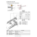
MX-1800N PAPER EXIT SECTION O – 1
MX-1800N
Service Manual
[O] PAPER EXIT SECTION
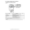
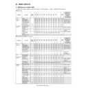
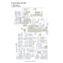
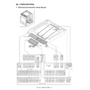
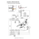
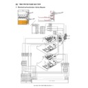
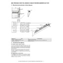
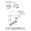
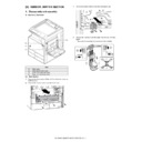
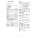
1. Electrical and mechanism relation diagram
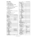
Signal name
Name
Function/Operation
FUM
Fusing drive motor
Drives the fusing unit.
HOPS
Shifter home position detection
Detects the shifter home position.
OSM
Shifter motor
Offsets the paper.
POD1
Fusing after detection
After fusing, paper exit from fusing section is detected.
POD2
Paper exit detection
Detects the exit paper.
POFM_F
Paper exit cooling fan motor (F side)
Cools the fusing unit.
POFM_R
Paper exit cooling fan motor (R side)
Cools the fusing unit.
POM
Paper exit drive motor
Drives the paper exit roller.
TFD2
Paper exit full detection
Detects face-down paper exit tray full.
R
SM-12p
P
CN6
B12B-PH-K-S
INT24V1
INT24V1
INT24V1
FUMB//
FUMA//
FUMB/
4
INT24V1
FUMA//
FUMB/
8
10
1
4
3
POMB//
FUMB//
POMB/
POMA/
12
INT24V1
2
6
11
9
10
12
9
1
2
5
6
3
7
11
10
10
7
12
1
2
5
6
3
4
9
8
8
11
POMB/
POMB//
FUMA/
POMA//
8
INT24V1
POMA/
DRIVER
MAIN
PWB
PWB
INT24V1
5
INT24V1
7
POMA//
FUMA/
INT24V1
1
POMA//
INT24V1
2
POMA/
POMB/
6
POMB//
3
INT24V1
4
5
FUMB//
1
FUMB/
INT24V1
4
5
2
INT24V1
3
FUMA/
6
FUMA//
P
DF1B-26p
S
CN13
B32B-PHDSS-B
DF11-4DP-SP1
DF11-8DP-SP2
DF11-6DP-SP1
DF11-6DP-SP1
12
10
2
13
3
2
1
4
6
8
2
4
/POFM_CNT
/POFM_CNT
/POFM_CNT
/POFM_CNT
5
7
3
1
1
5
6
4
3
2
1
5
6
4
3
2
D-GND
D-GND
D-GND
D-GND
D-GND
D-GND
5VNPD
5VNPD
5VNPD
5VNPD
5VNPD
5VNPD
P-GND
P-GND
P-GND
P-GND
POFM_V
POFM_V
POFM_V
POFM_V
12
POD2
13
/OSM_B
POD2
/OSM_A
14
HOPS
16
15
TFD2
/OSM_XA
P-GND
/OSM_XB
24V2
POFM_LD2
14
POD1
14
15
HOPS
16
17
12
12
18
11
11
P-GND
7
/POFM_CNT
POFM_V
/POFM_CNT
19
15
POFM_LD1
2
7
6
17
7
/OSM_A
3
/OSM_XB
4
5
5
POFM_LD1
9
TFD2
POFM_LD2
/OSM_B
8
2
5
4
24
8
9
9
21
22
22
9
/OSM_XA
3
13
11
5VNPD
D-GND
POD1
D-GND
16
5VNPD
17
1
24V2
1
6
POFM_V
PCU PWB
D-GND
3
HOPS
2
5VNPD
1
D-GND
3
POD1
2
5VNPD
1
3
POD2
5VNPD
2
1
D-GND
5VNPD
3
D-GND
1
TFD2
2
R
SM6P
P
1
24V2
/OSM_A
2
/OSM_XB
/OSM_XA
/OSM_XA
4
3
4
2
3
3
/OSM_B
1
5
5
PHNR-4-H,BU04P-TR-P-H
1
POFM_V
4
2
/POFM_CNT
3
3
P-GND
2
4
POFM_LD1
1
PHNR-4-H,BU04P-TR-P-H
1
POFM_V
2
/POFM_CNT
P-GND
4
POFM_LD2
4
3
2
1
3
2
1
3
TFD2
HOPS
OSM
POD2
POM
POD1
1
FUM
POFM_R
POFM_F
2
3
MX-1800N PAPER EXIT SECTION O – 2
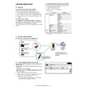
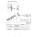
2. Operational descriptions
A. Paper exit section
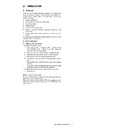
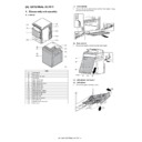
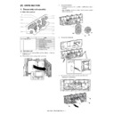
• Paper transported from the fusing section is passed to the trans-
port roller 13 which is driven by the paper exit drive motor and to
the paper exit roller 1, then discharged to the inner tray.
the paper exit roller 1, then discharged to the inner tray.
• When paper is discharged to the right tray, it is passed to the
paper exit roller 1 and the paper exit drive motor is reversely
rotated, and paper is passed over the ADU reverse gate and dis-
charged to the right tray.
rotated, and paper is passed over the ADU reverse gate and dis-
charged to the right tray.
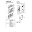
3. Disassembly and assembly
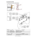
A. Paper exit section
(1) Paper exit unit
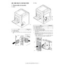
1) Remove the paper exit unit, and disconnect the connector.
a. Exit paper full detection sensor/
b. Shifter home position detection sensor
1)
1)
Remove the paper exit unit.
c. Paper exit detection sensor /
d. After-fusing sensor
1)
1)
Remove the paper exit unit.
2)
Paper exit sensor (A), after-fusing sensor (B)
e. Paper exit cooling fan motor
1)
1)
Remove the paper exit unit.
2)
Remove the exhaust fan duct.
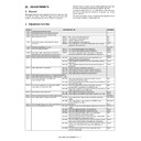
No.
Name
Function/Operation
1
Transport roller 9 (Drive)
Transports the paper from the fixing roller to the transport roller 13.
2
Transport roller 13 (Drive)
Paper transported from the transport roller 9 is transported to the paper exit roller 1. / Paper is
transported to the duplex (ADU) section.
transported to the duplex (ADU) section.
3
Paper exit roller 1 (Drive)
Paper is discharged. / Paper is transported to the right paper exit tray. / Paper is transported to the
duplex (ADU) section.
duplex (ADU) section.
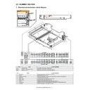
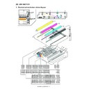
Unit
Parts
Maintenance
(1)
Paper exit
unit
unit
a
Exit paper full detection sensor
b
Shifter home position detection
sensor
sensor
c
Paper exit detection sensor
d
After-fusing sensor
e
Paper exit cooling fan motor
f
Discharge brush
g
Shifter motor
h
Paper exit roller 1 (Drive)
{
i
Fusing drive motor
j
Paper exit drive motor
k
Transport roller 13 (Drive)
{
l
Transport roller 9 (Drive)
{
m
Discharge brush
n
Paper exit filter
(1)
(1)-l
(1)-k
(1)-d
(1)-a (1)-b
(1)-g
(1)-j
(1)-i
(1)-f
(1)-e
(1)-h
(1)-e
(1)-c
(1)-m
(1)-n
(1)-n
1
2
A
B
MX-1800N PAPER EXIT SECTION O – 3
3) Remove the paper exit cooling fan motor.
f. Discharge brush
1) Remove the paper exit unit.
2) Remove the exhaust fan duct.
3) Remove the discharge grounding plate, and remove the dis-
1) Remove the paper exit unit.
2) Remove the exhaust fan duct.
3) Remove the discharge grounding plate, and remove the dis-
charge brush.
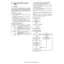
* Discharge brush attachment reference
When attaching the discharge brush, attach it along the
shifter PG.
shifter PG.
g. Shifter motor
1) Remove the paper exit unit.
2) Disconnect the connector and the grounding terminal, and
1) Remove the paper exit unit.
2) Disconnect the connector and the grounding terminal, and
remove the snap band. Remove the slide motor unit.
3)
Remove the shifter motor.
h. Paper exit roller 1 (Drive)
1)
1)
Remove the paper exit unit.
2)
Remove the exhaust fan duct.
3)
Remove the slide motor unit.
4)
Remove the parts. Slide the bearing, and remove the shifter
unit.
unit.
5)
Remove the parts, and remove the paper exit roller 1 (drive).
i. Fusing drive motor
1)
1)
Remove the paper exit unit.
2)
Remove the fusing drive motor.
1
2
1
2
1
2
3
4
MX-1800N PAPER EXIT SECTION O – 4
j. Paper exit drive motor
1) Remove the paper exit unit.
2) Remove the paper exit drive motor.
1) Remove the paper exit unit.
2) Remove the paper exit drive motor.
k. Transport roller 13 (Drive)
1) Remove the paper exit unit.
2) Remove the slide motor unit.
3) Remove the paper exit drive unit.
4) Remove the E-ring, the reverse drive belt, and the pulley.
1) Remove the paper exit unit.
2) Remove the slide motor unit.
3) Remove the paper exit drive unit.
4) Remove the E-ring, the reverse drive belt, and the pulley.
5) Remove the E-ring and the bearing, and remove the transport
roller 13 (Drive).
l. Transport roller 9 (Drive)
1) Remove the paper exit unit.
2) Remove the slide motor unit.
3) Remove the paper exit drive unit.
4) Remove the parts, and remove the transport roller 9 (Drive).
1) Remove the paper exit unit.
2) Remove the slide motor unit.
3) Remove the paper exit drive unit.
4) Remove the parts, and remove the transport roller 9 (Drive).
m. Discharge brush
1)
1)
Remove the paper exit unit.
2)
Remove the discharge brush.
* When attaching the discharge brush, attach it to the attachment
reference.
n. Paper exit filter
1)
1)
Open the right door.
2)
Open the filter holding sheet, and remove the paper exit filter.
0
㨪0.5mm
0
㨪0.5mm
1
1
2
2
Display

