Sharp MX-1800N (serv.man22) Service Manual ▷ View online
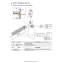
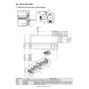
MX-1800N OPERATION PANEL B – 1
MX-1800N
Service Manual
[B] OPERATION PANEL
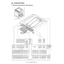
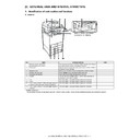
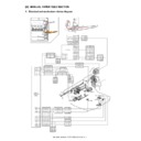
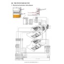
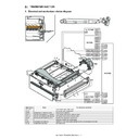
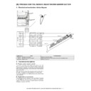
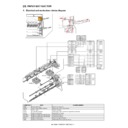
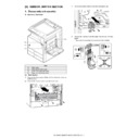
1. Electrical and mechanism relation diagram
CN136
B6P-PH-K-S
FG
24VEXT
5
/SIZE_LED1
1
D-GND
2
OCSW
3
5VEXT
OCSW
D-GND
24VEXT
1
2
3
5VEXT
/SIZE_LED1
6
/SIZE_LED2
4
/SIZE_LED2
F-GND
CN135
CN1
CN2
B6B-PH-SM3-TB
CN3
CN1
S3B-PH-K-S
52030-2629
52610-2671
CN125
CN1
CN3
52746-1570
CN4
04FM-1.0SP-1.9-GW-TF
CN2
CN1
S3B-PH-SM4-TB
S3B-PH-K-S
LCD INVERTOR
PWB
52030-3029
52271-3090
CN2
S02(8.0)B-BHS
MFP OPE-P
PWB
LVDS-P PWB
D-GND
1
1
D-GND
Y1CN
2
2
Y1CN
X1CN
3
3
X1CN
Y2CN
4
4
Y2CN
X2CN
5
5
X2CN
CN_CHK_IN(LCD)
66
CN_CHK_IN(LCD)
/CCFT1
7
7
/CCFT1
24V_EXT
9
9
24V_EXT
NC
24V_EXT
3
1
BACK LIGHT
PWRSW
P-GND
10
10
P-GND
NC
8
8
SC_TEMP
11
11
SC_TEMP
AVCC
1
2
1
2
AVCC
VCONT
13
13
VCONT
VEEON
14
14
VEEON
24V_EXT
3.3V_EXT
15
15
3.3V_EXT
D-GND
2
2
D-GND
/CCFT
DISP
16
16
DISP
1
3
/CCFT
D-GND
17
17
D-GND
3
/XL(X2)
4
LCD_DAT0-
18
18
LCD_DAT0-
LCD_DAT0+
1
9
1
9
L
CD_DAT0+
D-GND
20
20
D-GND
LCD_DAT1-
21
21
LCD_DAT1-
22
22
LCD_DAT1+
YH(Y2)
/YL(Y1)
D-GND
1
D-GND
23
23
D-GND
XH(X1)
2
LCD_DAT1+
VEE
LCD_DAT2-
24
24
LCD_DAT2-
LCD_DAT2+
2
5
2
5
L
CD_DAT2+
D-GND
26
26
D-GND
LCD_CLK-
27
27
LCD_CLK-
15
1
VEE
LCD_CLK+
28
28
LCD_CLK+
DISP
14
2
DISP
CN_CHK_OUT
29
29
CN_CHK_OUT
D-GND
13
3
D-GND
D3
D-GND
30
30
D-GND
12
4
D
3
D2
11
5
D
2
10
6
D-GND
D1
9
7
D1
D0
8
8
D0
D-GND
1
2
6
D-GND
3.3V_EXT
7
9
3.3V_EXT
5VO
2
25
5VO
M6
1
0
M
D-GND
3
2
4
D-GND
D-GND
5
1
1
D-GND
WU_LED
4
2
3
W
U_LED
CP
4
1
2
C
P
POW_LED
5
2
2
POW_LED
D-GND
3
1
3
D-GND
n
INFO_LED
6
21
n
INFO_LED
LP
2
1
4
L
P
n
W
U_KEY
7
2
0
n
WU_KEY
VO
1
1
5
V
O
n
P
WRSW
8
1
9
n
PWRSW
D-GND
9
1
8
D-GND
/BZR
1
0
1
7
/BZR
/F3
11
16
/F3
/F2
12
15
/F2
/F1
13
14
/F1
/F0
14
13
/F0
D-GND
3
1
D-GND
SEG2
15
12
SEG2
D-GND
2
2
D-GND
SEG1
16
11
SEG1
n
P
WRSW
1
3
n
P
WRSW
SEG0
17
10
SEG0
/KEYIN
1
8
9
/KEYIN
PDSEL2
1
9
8
PDSEL2
PDSEL1
2
0
7
PDSEL1
D-GND
6
6
D-GND
D-GND
PDSEL0
2
1
6
PDSEL0
PD
22
5
P
D
PD
5
5
PD
5VN
4
4
PDSEL1
PDSEL2
3
3
P
DSEL2
5VN
5VN
2
4
3
5VN
1
1
PDSEL0
3.3V
25
2
3
.3V
PDSEL1
2
2
D-GND
26
1
D-GND
PDSEL0
D-GND
23
4
SCN-CNT PWB
LCD
TOUCH PANEL
1
CCFT+
2
/CCFT
OCSW
1
3
2
4
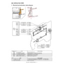
MX-1800N OPERATION PANEL B – 2
2. Operational descriptions
A. Outline
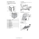
The operation panel unit is composed of the MFP OPE-P PWB, the
LCD INV PWB/LVDS PWB, the LCD unit, and the operation keys,
and is used to operate the machine and to set and display the
machine status.
The MFP OPE-P PWB is connected to the document detection light
receiving PWB for detecting the document size. It receives light
from the document detection light emitting PWB attached to the
rear frame, detecting the document size.
The power switch of the operation panel supplies the ON/OFF con-
trol signal of the DC power source.
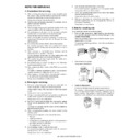
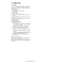
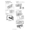
3. Disassembly and assembly
A. Operation panel section
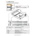
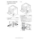
(1) Operation panel unit
1)
Remove the paper exit cover and the upper cabinet left.
2)
Remove the front cabinet upper and the operation panel base
plate.
plate.
3)
Remove each cables and the grounding sheet.
4)
Remove the operation panel unit.
a. LCD INV PWB /
b. LVDS PWB
1)
1)
Remove the operation panel unit.
2)
Remove the LCD INV PWB (A). Remove the LVDS PWB (B).
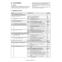
Signal
Name
Function/Operation
OCSW
Original cover SW
Timing switch for document size detection
PWRSW
Operaton panel power supply switch
Outputs the DC power supply ON/OFF control signal.
No.
Name
Function/Operation
1
MFP OPE-P PWB
Detects the key pressed on the operation panel.
2
LCD INV PWB/LVDS PWB
Drives LCD and the backlight, and controls the touch-panel.
3
Document detection light receiving PWB
Receives the light from the document detection light emitting PWB, and detects the document size.
4
Document detection light emitting PWB
Emits light for document size detection.
Unit
Parts
(1)
Operation panel unit
a
LCD INV PWB
b
LVDS PWB
c
LCD module
d
Touch panel
e
POWER SW PWB
f
MFP OPE-P PWB
(1)-e
(1)-f
(1)-a
(1)-d
(1)-c
(1)-b
(1)
B
A
MX-1800N OPERATION PANEL B – 3
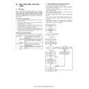
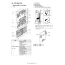
c. LCD module
1) Remove the operation panel unit.
2) Remove the LCD holder.
1) Remove the operation panel unit.
2) Remove the LCD holder.
3) Remove the LCD module.
d. Touch panel
1) Remove the operation panel unit.
2) Remove the LCD unit. Remove the flat cable.
1) Remove the operation panel unit.
2) Remove the LCD unit. Remove the flat cable.
3)
Remove the touch panel.
e. POWER SW PWB
1)
1)
Remove the operation panel unit.
2)
Remove the POWER SW PWB.
f. MFP OPE-P PWB
1)
1)
Remove the operation panel unit.
2)
Remove the POWER SW PWB.
3)
Remove the grounding sheet, and remove the MFP OPE-P
PWB.
PWB.
Display

