|
|
AR-M700 (serv.man7)
ALL DATA
Service Manual
|
127
|
50.95 MB
|
|
|
AR-M700 (serv.man8)
CIRCUIT DIAGRAM
Service Manual
|
127
|
17.27 MB
|
|
|
AR-M700 (serv.man9)
Cover, contents (caution note lead free solder info)
Service Manual
|
7
|
311.96 KB
|
|
|
AR-M700 (serv.man10)
Outline
Service Manual
|
3
|
338.69 KB
|
|
|
AR-M700 (serv.man11)
Configuration
Service Manual
|
2
|
75 KB
|
|
|
AR-M700 (serv.man12)
Specifications
Service Manual
|
16
|
242.97 KB
|
|
|
AR-M700 (serv.man13)
Consumable parts
Service Manual
|
6
|
60.57 KB
|
|
|
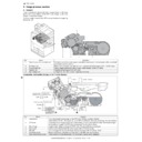
AR-M700 (serv.man14)
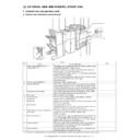
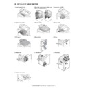
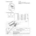
External view and internal structure
Service Manual
|
24
|
1.76 MB
|
|
|
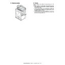
AR-M700 (serv.man15)
Details of each section - 1 Operation panel section
Service Manual
|
4
|
1.23 MB
|
|
|
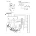
AR-M700 (serv.man16)
Details of each section - 2 Paper feed, paper transport
Service Manual
|
25
|
4.58 MB
|
|
|
AR-M700 (serv.man18)
Details of each section - 3 Laser scan unit
Service Manual
|
3
|
438.94 KB
|
|
|
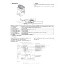
AR-M700 (serv.man19)
Details of each section - 4 Image process section
Service Manual
|
26
|
5.65 MB
|
|
|
AR-M700 (serv.man20)
Details of each section - 5 Scanner section
Service Manual
|
12
|
1.99 MB
|
|
|
AR-M700 (serv.man21)
Details of each section - 6 Fusing section
Service Manual
|
12
|
2.86 MB
|
|
|
AR-M700 (serv.man22)
Details of each section - 7 Spf section
Service Manual
|
20
|
4.09 MB
|
|
|
AR-M700 (serv.man23)
Details of each section - 8 Drive section
Service Manual
|
13
|
4.17 MB
|
|
|
AR-M700 (serv.man24)
Details of each section - 9 Filters, 10 PWB section
Service Manual
|
5
|
1.3 MB
|
|
|
AR-M700 (serv.man25)
Details of each section - 11 Power section, 12 Fan moto
Service Manual
|
7
|
2.34 MB
|
|
|
AR-M700 (serv.man26)
Setting and adjustments
Service Manual
|
43
|
2.52 MB
|
|
|
AR-M700 (serv.man27)
Simulation
Service Manual
|
97
|
948.19 KB
|
|
|
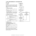
AR-M700 (serv.man28)
Self diag message and troubleshooting
Service Manual
|
38
|
292.59 KB
|
|
|
AR-M700 (serv.man29)
ROM version-up method
Service Manual
|
6
|
265.1 KB
|
|
|
AR-M700 (serv.man30)
Maintenance list
Service Manual
|
15
|
1.66 MB
|
|
|
AR-M700 (serv.man31)
Other
Service Manual
|
14
|
1.08 MB
|
|
|
AR-M700 (serv.man32)
Electric diagram
Service Manual
|
16
|
359 KB
|
|
|
AR-M700 (serv.man33)
Signal name list
Service Manual
|
11
|
117.34 KB
|

|
AR-M700
ARM550 620 700 Mac PPD for MacOS 10.1, 10.2, 10.3, 10.4, 10.5 and 10.6. Mac OS
Drivers
|
|
6.62 MB
|

|
AR-M700 (serv.man173)
ARM236 256 276 316 351 451 550 620 700 PS Driver for Windows Vista 64Bit. Version 801a WHQL signed. Windows Vista
Drivers
|
|
10.76 MB
|

|
AR-M700 (serv.man174)
Windows Vista PCL6 64 Bit Driver. Windows Vista
Drivers
|
|
5.86 MB
|

|
AR-M700 (serv.man175)
Windows Vista PCL6 Driver. This diver can be used in conjunction with 64 Bit printer driver. Windows Vista
Drivers
|
|
5.17 MB
|

|
AR-M700 (serv.man176)
Windows 2000 PCL6 64 Bit Driver. Windows 2000
Drivers
|
|
5.86 MB
|

|
AR-M700 (serv.man177)
Windows 2000 PCL6 Driver. This diver can be used in conjunction with 64 Bit printer driver. Windows 2000
Drivers
|
|
5.17 MB
|

|
AR-M700 (serv.man178)
ARM236 256 276 316 351 451 550 620 700 PS Driver for Windows XP 64Bit. Version 801a WHQL signed. Windows XP
Drivers
|
|
10.76 MB
|

|
AR-M700 (serv.man179)
Windows XP PCL6 64 Bit Driver. Windows XP
Drivers
|
|
5.86 MB
|

|
AR-M700 (serv.man180)
Windows XP PCL6 Driver. This diver can be used in conjunction with 64 Bit printer driver. Windows XP
Drivers
|
|
5.17 MB
|
|
|
AR-M700 (serv.man34)
ARM550 620 700 Parts Guide (Revised March 2011)
Service Manual / Parts Guide
|
127
|
15.66 MB
|
|
|
AR-M700 (serv.man35)
ARM550 620 700 Parts Guide (Revised)
Service Manual / Parts Guide
|
127
|
17.99 MB
|
|
|
AR-M700 (serv.man36)
Parts Guide, sections 51-59
Service Manual / Parts Guide
|
12
|
1.81 MB
|
|
|
AR-M700 (serv.man37)
Complete Parts Guide.
Service Manual / Parts Guide
|
127
|
15.54 MB
|
|
|
AR-M700 (serv.man38)
Parts Guide (complete).
Service Manual / Parts Guide
|
127
|
15.49 MB
|
|
|
AR-M700 (serv.man39)
Parts Change
Service Manual / Parts Guide
|
1
|
20.29 KB
|
|
|
AR-M700 (serv.man40)
Parts Change
Service Manual / Parts Guide
|
1
|
21.28 KB
|
|
|
AR-M700 (serv.man41)
Parts Change
Service Manual / Parts Guide
|
1
|
16.7 KB
|
|
|
AR-M700 (serv.man42)
Parts Change
Service Manual / Parts Guide
|
3
|
27 KB
|
|
|
AR-M700 (serv.man43)
Parts Change
Service Manual / Parts Guide
|
8
|
465.49 KB
|
|
|
AR-M700 (serv.man44)
MFP controller PWB, 14 - AC PWB unit.
Service Manual / Parts Guide
|
7
|
132.39 KB
|
|
|
AR-M700 (serv.man45)
Information of parts change to sections 14-SPF frame section, 34-Duct section, 46-Fusing unit 1, 47-Fusing unit 2, 48-Fusing unit3, 54-Delivery reverse 1, 55-Delivery reverse 2.
Service Manual / Parts Guide
|
13
|
1.54 MB
|
|
|
AR-M700 (serv.man46)
Information of parts changes to section 79 Packing material accessories.
Service Manual / Parts Guide
|
4
|
386.69 KB
|
|
|
AR-M700 (serv.man47)
Information of parts change to sections 2 Exteriors 2, 8 SPF Pick up unit, 13 SPF Drive section, 20 3 4 Paper feed section1, 29 Manual paper feed unit 2, 37 DVunit 2, 46 Fusing unit 1, 49 Left door 1, 50 Left door 2, 70 Rear frame section 2, 71 Rear frame section 3, 77 Harness section, 79 Packing material accessories
Service Manual / Parts Guide
|
23
|
3.09 MB
|
|
|
AR-M700 (serv.man48)
MFP Controller PWB
Service Manual / Parts Guide
|
6
|
65.8 KB
|
|
|
AR-M700 (serv.man49)
Part Guide for ARM550 620 700 PWB's
Service Manual / Parts Guide
|
37
|
565.97 KB
|
|
|
AR-M700 (serv.man50)
Rear Frame section 3.
Service Manual / Parts Guide
|
3
|
592.3 KB
|
|
|
AR-M700 (serv.man51)
Scanner relay PWB, 13 - PCU PWB.
Service Manual / Parts Guide
|
6
|
63.69 KB
|
|
|
AR-M700 (serv.man52)
1 2 Paper feed tray 1, 41 - Process unit 2, 42 - Process unit 3, 47 - Fusing unit 2, 48 - Fusing unit 3, 54 - Delivery reverse 1, 55 - Delivery reverse 2.
Service Manual / Parts Guide
|
11
|
1.48 MB
|
|
|
AR-M700 (serv.man53)
Optical Frame 1, 36 - DV Unit 1, 38 - Toner Hopper Unit, 42 - Process Unit 3, 53 - Left Door 5, 68 - Front Frame Section, 71 - Rear Frame Section 3.
Service Manual / Parts Guide
|
14
|
1.74 MB
|
|
|
AR-M700 (serv.man54)
Operation panel section, 48 - Fusing unit, 76 - Power supply section, 78 - MFP controller section, 79 - Packing material accessories.
Service Manual / Parts Guide
|
9
|
978.06 KB
|
|
|
AR-M700 (serv.man55)
Operation Panel Section, 7 - SPF Tray, 12 - SPF CIS delivery section, 20 - 3 4 Paper feed section 1, 22 - 3 4 paper feed section 3, 24 - 1 2 paper feed tray section 2, 25 - 1 2 paper feed tray section 3, 28 - Manual paper feed unit 1, 29 - Manual paper feed unit 2, 30 - Manual paper feed unit 3, 34 - Duct unit, 35 - PS roller, 45 - Transfer unit, 55 - Delivery reverse 2.
Service Manual / Parts Guide
|
21
|
2.16 MB
|
|
|
AR-M700 (serv.man56)
Manual Paper FeedingTray, 48 - Fusing Unit 3.
Service Manual / Parts Guide
|
4
|
389.69 KB
|
|
|
AR-M700 (serv.man57)
Operation Panel Section, 36 - DV Unit 1, 37 - DV Unit 2, 38 - Toner Hopper Unit, 48 - Fusing Unit 3, 53 - Left Door 5, 54 - Delivery Reverse 1, 71 - Rear Frame Section 3, 76 - Power Supply Section.
Service Manual / Parts Guide
|
15
|
1.96 MB
|
|
|
AR-M700 (serv.man58)
Information of parts change, sections 17-Optical frame unit 2, 25-1 2 paper feed tray 3, 35-PS roller, 36-DV unit 1, 37-DV unit 2, 48-Fusing unit 3, 51-Left door 3, 57-Main drive, 59-Drum drive 2, 60-1 2 Paper feed drive unit 1, 61-1 2 Paper feed drive unit 2, 63-Fusing drive unit, 64-3 4 Drive unit, 70-Rear frame section 2, 74-Interface pass unit 1.
Service Manual / Parts Guide
|
27
|
3.41 MB
|
|
|
AR-M700 (serv.man59)
Information of parts change, sections 12-SPF CIS unit delivery unit, 18-Lamp unit, 37-DV unit 2, 39-MC unit, 42-Process unit 3, 48-Fusing unit 3, 63-Fusing drive unit, 67-Frame section, 71-Rear frame section 3, 79-Packing materials accessories.
Service Manual / Parts Guide
|
19
|
2.59 MB
|
|
|
AR-M700 (serv.man60)
Information of Parts changes, section 67-Frame Section.
Service Manual / Parts Guide
|
3
|
484.82 KB
|
|
|
AR-M700 (serv.man61)
Information of Parts changes, sections 5-SPF Exteriors, 16 Optical Frame 1, 17-Optical Frame 2, 42-Process Unit 3, 43-Process Unit 4, 47-Fusing Unit 2, 49 Left Door 1, 66 Controller Box.
Service Manual / Parts Guide
|
15
|
1.88 MB
|
|
|
AR-M700 (serv.man62)
SPF CIS Delivery Section, 16 - Optical Frame 1, 38 - Toner Hopper Unit, 42 - Process Unit 3, 48 - Fusing Unit 3, 52 - Left Door 4, 58 - Drum Drive 1, 75 - Interface Pass Unit 2.
Service Manual / Parts Guide
|
15
|
1.54 MB
|
|
|
AR-M700 (serv.man63)
Update to the parts guide, 21 3 4 paper feed section 2, 36 DV unit 1, 39, MCU unit, 47 Fusing unit 2, 48 Fusing unit 3, 67 Frame unit.
Service Manual / Parts Guide
|
11
|
1.35 MB
|
|
|
AR-M700 (serv.man64)
Update to the parts guide November 04-The following sections have been updated, 12-SPF CIS and Delivery Unit, 16-Optional Frame 1, 38-Toner Hopper Unit, 42-Process Unit 3, 48-Fusing Unit3, 52-Left Door 4, 58-Drum Drive 1, 75-Interface Pass Unit 2.
Service Manual / Parts Guide
|
15
|
1.54 MB
|
|
|
AR-M700 (serv.man3)
Parts Change
Service Manual / Specification
|
1
|
16.7 KB
|
|
|
AR-M700 (serv.man4)
Parts Change
Service Manual / Specification
|
3
|
27 KB
|
|
|
AR-M700 (serv.man5)
Parts Change
Service Manual / Specification
|
8
|
465.49 KB
|

|
AR-M700 (serv.man6)
ARM550 620 700 BERTL Test reports and Certificates
Service Manual / Specification
|
|
4.35 MB
|
|
|
AR-M700 (serv.man99)
Reinforcement of the Delivery Actuator
Service Manual / Technical Bulletin
|
2
|
271.3 KB
|
|
|
AR-M700 (serv.man100)
ARE-1085 Modified waste toner transfer pipe due to Leakage.
Service Manual / Technical Bulletin
|
2
|
108.21 KB
|
|
|
AR-M700 (serv.man101)
Ref ARE1010 REMOVAL OF SCREWS FROM THE DUCT AND REAR FRAME 2 3.
Service Manual / Technical Bulletin
|
2
|
407.03 KB
|
|
|
AR-M700 (serv.man102)
REF ARE 1002 PREVENTION OF THE MANUAL PAPER FEED UNIT SEPARATION TORQUE LIMITER COMING LOOSE.
Service Manual / Technical Bulletin
|
2
|
182.34 KB
|
|
|
AR-M700 (serv.man103)
ARE 991 DAMAGE TO THE 1ST 2ND PAPER FEED DRIVE UNIT AND THE DRUM DRIVE UNIT SHAFTS.
Service Manual / Technical Bulletin
|
3
|
576.33 KB
|
|
|
AR-M700 (serv.man104)
Ref ARE 984 IMAGE TROUBLE (WHITE STREAKS) CAUSED BY GRINDING DOWN OF THE DRUM.
Service Manual / Technical Bulletin
|
2
|
597.25 KB
|
|
|
AR-M700 (serv.man105)
Ref CCE779 AR-CF2 COUNTERMEASURES FOR JAM (HI_SEN_S, ETC.)RESULTING FROM MISALIGNED SPRING HOOK SECTION OF DELIVERY SENSOR LEVER.
Service Manual / Technical Bulletin
|
2
|
342.03 KB
|
|
|
AR-M700 (serv.man106)
Ref ARE971 MX-F16 NEW SERVICE PARTS FOR THE SADDLE-STITCH FINISHER EJECTION TRAYS
Service Manual / Technical Bulletin
|
6
|
2.24 MB
|
|
|
AR-M700 (serv.man107)
ARE-969 IMPROVEMENT BY REMOVING THE SHAFT BEARINGS OF THE PS ROLLER REAR SIDE.
Service Manual / Technical Bulletin
|
2
|
154.15 KB
|
|
|
AR-M700 (serv.man108)
ARE-962 F1-46 TROUBLE CODE OCCURRENCE AFTER JAM PROCESSING.
Service Manual / Technical Bulletin
|
2
|
290.02 KB
|
|
|
AR-M700 (serv.man109)
REF ARE960 PRECAUTIONS WHEN REPLACING THE DV SIDE SEAL
Service Manual / Technical Bulletin
|
3
|
1.26 MB
|
|
|
AR-M700 (serv.man110)
ARE-957 PREVENTION OF THE COOLING FAN MOTOR BEARING FIXING FROM BEING STRIPPED
Service Manual / Technical Bulletin
|
2
|
195.25 KB
|
|
|
AR-M700 (serv.man111)
ARE-956 IMPROVEMENTS MADE TO THE PROCESS UNIT AGAINST TONER SPLASHING ON THE SUB-BLADE
Service Manual / Technical Bulletin
|
3
|
1.26 MB
|
|
|
AR-M700 (serv.man112)
REF ARE-947 SUB-HEATER CLEANING FELT PLATE CHANGE, TO PREVENT PEALING OF THE FELT FROM PLATE.
Service Manual / Technical Bulletin
|
2
|
270.86 KB
|
|
|
AR-M700 (serv.man113)
REF ARE-945 ALTERATION TO THE MANUAL PAPER FEED BASE TO PREVENT DAMAGE TO THE BOSS.
Service Manual / Technical Bulletin
|
2
|
245.2 KB
|
|
|
AR-M700 (serv.man114)
ARE936 IMPROVEMENT AGAINST TONER SPLATTERING FROM UNDER THE SUB BLADE.
Service Manual / Technical Bulletin
|
2
|
355.35 KB
|
|
|
AR-M700 (serv.man115)
CHANGE OF INITIAL VALUES OF PREHEAT MODE AND AUTO POWER SHUT-OFF MODE OF ENERGY STAR VER1.1
Service Manual / Technical Bulletin
|
2
|
20.01 KB
|
|
|
AR-M700 (serv.man116)
CHANGE OF INITIAL VALUES OF PREHEAT MODE AND AUTO POWER SHUT-OFF MODE OF ENERGY STAR VER1.1
Service Manual / Technical Bulletin
|
2
|
20.04 KB
|
|
|
AR-M700 (serv.man117)
Ref ARE916 IMPROVEMENT IN PAPER FEEDING PERFOMANCE OF SPF.
Service Manual / Technical Bulletin
|
2
|
94.05 KB
|
|
|
AR-M700 (serv.man118)
REF AER900 COUNTER MEASURE AGAINST REVERSE PRESSURE RELEASE LEVER COMING AWAY FROM ITS HOOK.
Service Manual / Technical Bulletin
|
1
|
106.88 KB
|
|
|
AR-M700 (serv.man119)
NEW SETUP PROCEDURE WHEN REPLACING DEVELOPER (SUPERSEDING BULLETIN DATED 1ST JULY 2008)
Service Manual / Technical Bulletin
|
1
|
69.32 KB
|
|
|
AR-M700 (serv.man120)
AR-F16 Saddle unit ROM UPGRADE
Service Manual / Technical Bulletin
|
1
|
25.71 KB
|
|
|
AR-M700 (serv.man121)
AR-F15 F16 ROM UPGRADE
Service Manual / Technical Bulletin
|
1
|
27.39 KB
|
|
|
AR-M700 (serv.man122)
ENHANCEMENT OF STRENGTH OF DSPF (SPF) ADJUST PLATES F R.
Service Manual / Technical Bulletin
|
2
|
409.12 KB
|
|
|
AR-M700 (serv.man123)
CHANGE TO THE TONER DENSITY REFERENCE SETUP PROCEDURE IN THE INSTALLATION MANUAL.
Service Manual / Technical Bulletin
|
2
|
171.43 KB
|
|
|
AR-M700 (serv.man124)
TONER CARTRIDGE NOT FITTING CORRECTLY, DUE TO THE TONER HOPPER CONNECTOR PLATE DEFORMING.
Service Manual / Technical Bulletin
|
2
|
285.57 KB
|
|
|
AR-M700 (serv.man125)
TONER CARTRIDGE NOT FITTING CORRECTLY, DUE TO THE TONER HOPPER CONNECTOR PLATE DEFORMING.
Service Manual / Technical Bulletin
|
2
|
171.43 KB
|
|
|
AR-M700 (serv.man126)
ARE882-F2-00 ETC. DUE TO POOR CONTACT BETWEEN TRANSFER AC TERMINAL AND TRANSFER ELECTRODE SPRING.
Service Manual / Technical Bulletin
|
2
|
343.86 KB
|
|
|
AR-M700 (serv.man127)
Counter Measures Taken When Copy lamp Is Not Switched On Due To Glass Being Charged
Service Manual / Technical Bulletin
|
2
|
85.72 KB
|
|
|
AR-M700 (serv.man128)
Strength Improvement Of The Output Axis Gear Of The Lift Motor A
Service Manual / Technical Bulletin
|
2
|
75.64 KB
|
|
|
AR-M700 (serv.man129)
FINISHER TRANSFER MOTOR FAILURE
Service Manual / Technical Bulletin
|
2
|
54.29 KB
|
|
|
AR-M700 (serv.man130)
ROM Version Update (17) Please See Bulletin For Details
Service Manual / Technical Bulletin
|
5
|
28.46 KB
|
|
|
AR-M700 (serv.man131)
Improvement Of The Fusing Unit
Service Manual / Technical Bulletin
|
6
|
169.37 KB
|

|
AR-M700 (serv.man132)
Improvment in initial low Density, Halftone density and such
Service Manual / Technical Bulletin
|
|
122.99 KB
|
|
|
AR-M700 (serv.man133)
LIFT UP MOTOR FAILURES ARE816
Service Manual / Technical Bulletin
|
2
|
229.08 KB
|
|
|
AR-M700 (serv.man134)
Part change information to fuser unit.
Service Manual / Technical Bulletin
|
3
|
163.25 KB
|
|
|
AR-M700 (serv.man135)
ROM version update..15
Service Manual / Technical Bulletin
|
2
|
65.87 KB
|
|
|
AR-M700 (serv.man136)
034-Change to new type flash ROM (ELEM)
Service Manual / Technical Bulletin
|
2
|
140.44 KB
|
|
|
AR-M700 (serv.man137)
033-Making LCD, FFC and LVDS INV board service parts available as a kit.
Service Manual / Technical Bulletin
|
2
|
58.31 KB
|
|
|
AR-M700 (serv.man138)
Improvement of the fusing unit.
Service Manual / Technical Bulletin
|
3
|
183.54 KB
|
|
|
AR-M700 (serv.man139)
Update to tech bulletins 048 (ARM550U M620U), 030 (ARM700U). Improvement for initial low density and halftone density.
Service Manual / Technical Bulletin
|
1
|
107.7 KB
|
|
|
AR-M700 (serv.man140)
Improvement for initial low density and halftone density.
Service Manual / Technical Bulletin
|
2
|
112.88 KB
|
|
|
AR-M700 (serv.man141)
Measures to prevent double feeding and noise from tandem sheet feeder.
Service Manual / Technical Bulletin
|
2
|
50.9 KB
|
|
|
AR-M700 (serv.man142)
ROM upgrade, only for when the ARLC7 is being installed.
Service Manual / Technical Bulletin
|
2
|
103.86 KB
|
|
|
AR-M700 (serv.man143)
Change in I F connectors for coin vendors.
Service Manual / Technical Bulletin
|
1
|
25.38 KB
|
|
|
AR-M700 (serv.man144)
ROM Upgrade..12
Service Manual / Technical Bulletin
|
3
|
12.56 KB
|
|
|
AR-M700 (serv.man145)
Additions to details described in simulation 62-10.
Service Manual / Technical Bulletin
|
1
|
36.83 KB
|
|
|
AR-M700 (serv.man146)
Measures against noise generated from the toner motor on the toner cartridge.
Service Manual / Technical Bulletin
|
2
|
39.39 KB
|
|
|
AR-M700 (serv.man147)
Improvement in halftone image quality.
Service Manual / Technical Bulletin
|
6
|
1.53 MB
|
|
|
AR-M700 (serv.man148)
Prevention of thermistor marks appearing on the upper fuser roller.
Service Manual / Technical Bulletin
|
1
|
18.02 KB
|
|
|
AR-M700 (serv.man149)
Prevention of the paper discharge actuator becoming detached.
Service Manual / Technical Bulletin
|
1
|
25.16 KB
|
|
|
AR-M700 (serv.man150)
To reduce paper skew or paper misfeeding when duplex copying printing.
Service Manual / Technical Bulletin
|
2
|
104.81 KB
|
|
|
AR-M700 (serv.man151)
Improvement to clear waste toner from the process unit.
Service Manual / Technical Bulletin
|
6
|
1.69 MB
|
|
|
AR-M700 (serv.man152)
Performance enhancements with ROM upgrade 10..v4.00
Service Manual / Technical Bulletin
|
31
|
2.85 MB
|
|
|
AR-M700 (serv.man153)
Remedy for U2-50 error that occurs when a security kit is installed.
Service Manual / Technical Bulletin
|
3
|
187.32 KB
|
|
|
AR-M700 (serv.man154)
016-Increase adhesion strength of the oil roller to the core shaft.
Service Manual / Technical Bulletin
|
2
|
49.66 KB
|
|
|
AR-M700 (serv.man155)
015- ROM upgrade (10)
Service Manual / Technical Bulletin
|
2
|
48.13 KB
|
|
|
AR-M700 (serv.man156)
014-Increased margins of detection of MPFD2 sensor in the interface pass unit.
Service Manual / Technical Bulletin
|
2
|
44.51 KB
|
|
|
AR-M700 (serv.man157)
013-Measures against misfeeding at POD1_N, due to breaking chipping of the upper fuser pawls and the drum pick off pawls.
Service Manual / Technical Bulletin
|
8
|
339.86 KB
|
|
|
AR-M700 (serv.man158)
012-Discontinued use of the one-way gear (30T) in the left-hand door unit.
Service Manual / Technical Bulletin
|
2
|
101.36 KB
|
|
|
AR-M700 (serv.man159)
011-Change of side seal R on the processing unit.
Service Manual / Technical Bulletin
|
1
|
60.63 KB
|
|
|
AR-M700 (serv.man160)
010-Prevention against indicating incorrect paper size on the manual paper feed tray.
Service Manual / Technical Bulletin
|
2
|
45.48 KB
|
|
|
AR-M700 (serv.man161)
009-Prevention of POD1_N misfeeds due to the paper being caught on the broken upper separator pawl of the fusing unit.
Service Manual / Technical Bulletin
|
1
|
42.72 KB
|
|
|
AR-M700 (serv.man162)
008-Adjustment required when the CIS unit or the CIS pwb is replaced.
Service Manual / Technical Bulletin
|
1
|
8.36 KB
|
|
|
AR-M700 (serv.man163)
007-Added protection has been added between the Document Detection Light-Receiving pwb and harness.
Service Manual / Technical Bulletin
|
2
|
155 KB
|
|
|
AR-M700 (serv.man164)
006-To prevent blur sections at the end of an A3 copy.
Service Manual / Technical Bulletin
|
1
|
7.49 KB
|
|
|
AR-M700 (serv.man165)
005-Improvement made to prevent rib of first second paper feed (tandem paper feed) from being broken.
Service Manual / Technical Bulletin
|
2
|
110.24 KB
|
|
|
AR-M700 (serv.man166)
004-Improvement of the reset ability of the conveyance sensors for the fifth tray interface and the manual bypass feeder.
Service Manual / Technical Bulletin
|
2
|
37.13 KB
|
|
|
AR-M700 (serv.man167)
003-Change in the MC cleaner handle.
Service Manual / Technical Bulletin
|
2
|
90.33 KB
|
|
|
AR-M700 (serv.man168)
002-H4-02 trouble.
Service Manual / Technical Bulletin
|
2
|
68.03 KB
|
|
|
AR-M700 (serv.man169)
ROM Upgrade .7
Service Manual / Technical Bulletin
|
2
|
35.37 KB
|

|
AR-M700 (serv.man66)
REF. ARE932 Energy Star ROM UPGRADE ... (18). WITH AR-P19 NON-ELEM
Driver / Update
|
|
222.52 KB
|

|
AR-M700 (serv.man67)
REF. ARE932 Energy Star ROM UPGRADE ... (18). WITH AR-P19 ELEM
Driver / Update
|
|
197.12 KB
|

|
AR-M700 (serv.man68)
REF. ARE932 Energy Star ROM UPGRADE ... (18). WITHOUT AR-P19 ELEM
Driver / Update
|
|
9.72 MB
|

|
AR-M700 (serv.man69)
REF. ARE932 Energy Star ROM UPGRADE ... (18). WITHOUT AR-P19 NON-ELEM
Driver / Update
|
|
9.72 MB
|

|
AR-M700 (serv.man70)
ARM550 620 700 OSA Firmware V5.d51 ELEM
Driver / Update
|
|
12.82 MB
|

|
AR-M700 (serv.man71)
ARM550 620 700 OSA Firmware V5.d51 Non ELEM
Driver / Update
|
|
12.81 MB
|

|
AR-M700 (serv.man72)
P19 Firmware Update For 'U' Version Models Vp4.05
Driver / Update
|
|
13.14 MB
|

|
AR-M700 (serv.man73)
P19 Firmware Update For 'U' Version Models (ELEM) Vp4.05
Driver / Update
|
|
13.15 MB
|

|
AR-M700 (serv.man74)
Firmware Update For 'U' Version Models Vu4.05
Driver / Update
|
|
10.61 MB
|

|
AR-M700 (serv.man75)
Firmware Update For 'U' Version Models (ELEM) Vu4.05
Driver / Update
|
|
10.62 MB
|

|
AR-M700 (serv.man76)
DSK Firmware October 2007
Driver / Update
|
|
13.38 MB
|

|
AR-M700 (serv.man77)
DSK Firmware October 2007 (ELEM)
Driver / Update
|
|
13.38 MB
|

|
AR-M700 (serv.man78)
Non-Elem type firmware. u4a.04
Driver / Update
|
|
10.72 MB
|

|
AR-M700 (serv.man79)
ARM550 620 700 OSA Firmware V5.51 Non ELEM
Driver / Update
|
|
13.72 MB
|

|
AR-M700 (serv.man80)
ARM550 620 700 OSA Firmware V5.51 ELEM
Driver / Update
|
|
13.73 MB
|

|
AR-M700 (serv.man81)
Firmware Update October 2006 NON elem without P19 (U version)
Driver / Update
|
|
547.75 KB
|

|
AR-M700 (serv.man82)
Firmware Oct 2006 Elem with P19
Driver / Update
|
|
13.13 MB
|

|
AR-M700 (serv.man83)
Firmware Oct 2006 Non Elem with P19
Driver / Update
|
|
13.13 MB
|

|
AR-M700 (serv.man84)
Firmware Update Oct 2006 elem Models
Driver / Update
|
|
13.13 MB
|

|
AR-M700 (serv.man85)
Rom Control No F00 - For U version models fitted with AR-P19 - Elem type firmware.(Main up to Vp4.04, Boot up to VM5.33A, PCU up to V03.11. Upgrade Utility and change details enclosed.
Driver / Update
|
|
13.31 MB
|

|
AR-M700 (serv.man86)
For U version models fitted with AR-P19 - Non-Elem type firmware.(Main up to Vp4.04, Boot up to VM5.33A, PCU up to V03.11. Upgrade Utility and change details enclosed.
Driver / Update
|
|
13.3 MB
|

|
AR-M700 (serv.man87)
For U version models (no P19 fitted) - Elem type firmware.(Main up to Vu4.04, Boot up to VM5.33A, PCU up to V03.11. Change details enclosed.
Driver / Update
|
|
10.78 MB
|

|
AR-M700 (serv.man88)
For U version models (no P19 fitted) - Non-Elem type firmware.(Main up to Vu4.04, Boot up to VM5.33A, PCU up to V03.11. Change details enclosed.
Driver / Update
|
|
10.77 MB
|

|
AR-M700 (serv.man89)
Common PC Fax Driver (v2.3.0.110) for Andromeda, Pegasus E, Tiger, Jupiter and Dragon Products.
Driver / Update
|
|
16.61 MB
|

|
AR-M700 (serv.man90)
ARM550 M620 M700 P19 firmware, ROM control F01 V4p.03, includes updated PCU (v03.10) and SCN (v02.10) for machine installed with ARP19. Improvement of initial low density and halftone density. Please read tech bulletins 048 and 049 (ARM550 M620), 030 and 031 (ARM700) or 007 (ARP19) for more details.
Driver / Update
|
|
13.09 MB
|

|
AR-M700 (serv.man91)
ARM550 M620 M700 firmware, PCU (V03.10) and SCN (V02.10). Improvement of initial low denity and halftone density. Please read tech bulletins 048 (ARM550 M620) or 030 (ARM700) for more details.
Driver / Update
|
|
280.98 KB
|

|
AR-M700 (serv.man92)
ARM550 M620 M700 firmware, ROM control no. F01 Vu4.03, includes updated PCU (v03.10) and SCN (v02.10), only for 'U'version machines. Improvement of initial low denity and halftone density. Please read tech bulletins 048 (ARM550 M620) or 030 (ARM700) for more details.
Driver / Update
|
|
10.56 MB
|

|
AR-M700 (serv.man93)
ARM550 620 700U firmware vu4.03 when an ARP19 is NOT installed, compatible for halftone image quality.
Driver / Update
|
|
10.67 MB
|

|
AR-M700 (serv.man94)
ARM550 620 700U firmware vp4.03 when an ARP19 is installed, compatible for halftone image quality.
Driver / Update
|
|
13.2 MB
|

|
AR-M700 (serv.man95)
ARM550 620 700U firmware vp4a.03 when an ARP19 is installed, compatible for halftone image quality and Batch Printing.
Driver / Update
|
|
13.22 MB
|

|
AR-M700 (serv.man96)
ARM550 620 700U firmware vu4.00, when an ARP19 is NOT installed.
Driver / Update
|
|
10.61 MB
|

|
AR-M700 (serv.man97)
ARM550 620 700U firmware vp4.00, to be installed when an ARP19 is fitted.
Driver / Update
|
|
13.13 MB
|

|
AR-M700 (serv.man98)
ARM550 ARM620 ARM700 Firmware Update Tool.
Driver / Update
|
|
113.84 KB
|
|
|
AR-M700 (serv.man2)
Handy Guide ARM550 620 700 Feb2005
Handy Guide
|
48
|
535.54 KB
|
|
|
AR-M700 (serv.man65)
Commands for selection of paper input and output trays. Including Escape codes, PJL commands and Postscript commands.
FAQ
|
66
|
274.11 KB
|
|
|
AR-M700 (serv.man170)
ARM620 DV msds
Regulatory Data
|
4
|
29.19 KB
|
|
|
AR-M700 (serv.man171)
ARM700 Safety Sheet
Regulatory Data
|
2
|
44.53 KB
|
|
|
AR-M700 (serv.man172)
ARM700 MSDS sheet
Regulatory Data
|
4
|
29.23 KB
|

