Sharp AR-M550 (serv.man4) Service Manual ▷ View online
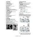
CAUTION
This laser radiation is not a danger to the skin, but when an exact focusing of the laser beam is achieved
on the eye’s retina, there is the danger of spot damage to the retina.
on the eye’s retina, there is the danger of spot damage to the retina.
The following cautions must be observed to avoid exposure of the laser beam to your eyes at the time of
servicing.
servicing.
1)
When a problem in the laser optical unit has occurred, the whole optical unit must be exchanged as a
unit, not as individual parts.
unit, not as individual parts.
2)
Do not look into the machine with the main switch turned on after removing the developer unit, toner
cartridge, and drum cartridge.
cartridge, and drum cartridge.
3)
Do not look into the laser beam exposure slit of the laser optical unit with the connector connected
when removing and installing the optical system.
when removing and installing the optical system.
4)
The middle frame contains the safety interlock switch.
Do not defeat the safety interlock by inserting wedges or other items into the switch slot.
+10 nm
–15 nm
–15 nm
Pulse times
North America: 55 cpm model (3.1
µ
s
±
3.1 ns)/7 mm
62 cpm model (3.1
µ
s
±
3.1 ns)/7 mm
70 cpm model (2.7
µ
s
±
2.7 ns)/7 mm
Europe:
55 cpm model (3.7
µ
s
±
3.7 ns)/7 mm
62 cpm model (3.7
µ
s
±
3.7 ns)/7 mm
70 cpm model (3.2
µ
s
±
3.2 ns)/7 mm
Output power:
Max 0.8 mW
Wave length:
785 nm
CAUTION
INVISIBLE LASER RADIATION,
WHEN OPEN AND INTERLOCKS DEFEATED.
AVOID EXPOSURE TO BEAM.
VORSICHT
UNSICHTBARE LASERSTRAHLUNG,
WENN ABDECKUNG GEÖFFNET UND
SICHERHEITSVERRIEGELUNG ÜBERBRÜCKT.
SICHERHEITSVERRIEGELUNG ÜBERBRÜCKT.
NICHT DEM STRAHL AUSSETZEN.
VARO !
AVATTAESSA JA SUOJALUKITUS
OHITETTAESSA OLET ALTTIINA
OHITETTAESSA OLET ALTTIINA
NÄKYMÄTTÖMÄLLE LASERSÄTEILYLLE ÄLÄ
KATSO SÄTEESEEN.
ADVARSEL
USYNLIG LASERSTRÅLNING VED ÅBNING, NÅR
SIKKERHEDSBRYDERE ER UDE AF
FUNKTION. UNDGÅ UDSAETTELSE FOR
FUNKTION. UNDGÅ UDSAETTELSE FOR
STRÅLNING.
VARNING !
OSYNLIG LASERSTRÅLNING NÄR DENNA DEL
ÄR ÖPPNAD OCH SPÄRREN ÄR URKOPPLAD.
BETRAKTA EJ STRÅLEN. – STRÅLEN ÄR
BETRAKTA EJ STRÅLEN. – STRÅLEN ÄR
FARLIG.
This product is a class 1 laser product that complies with 21CFR 1040 of the CDRH standard and
IEC825. This means that this machine does not produce hazardous laser radiation. The use of controls,
adjustments or performance of procedures other than those specified herein may result in hazardous
radiation exposure.
IEC825. This means that this machine does not produce hazardous laser radiation. The use of controls,
adjustments or performance of procedures other than those specified herein may result in hazardous
radiation exposure.
CLASS 1
LASER PRODUCT
LASER KLASSE 1
CLASS 1
LASER PRODUCT
LASER KLASSE 1
CAUTION
VORSICHT
ADVARSEL
ADVERSEL
VARNING
VARO!
VORSICHT
ADVARSEL
ADVERSEL
VARNING
VARO!
INVISIBLE LASER RADIATION WHEN OPEN AND INTERLOCKS DEFEATED.
AVOID EXPOSURE TO BEAM.
AVOID EXPOSURE TO BEAM.
Laserstrahl
UNSICHTBARE LASERSTRAHLUNG WENN ABDECKUNG GEÖFFNET UND
SICHERHEITSVERRIEGELUNG ÜBERERÜCKT. NICHT DEM STRAHL AUSSETZEN.
SICHERHEITSVERRIEGELUNG ÜBERERÜCKT. NICHT DEM STRAHL AUSSETZEN.
USYNLIG LASERSTRÅLING VED ÅBNING, NÅR SIKKERHEDSAFBRYDERE ER
UDE AF FUNKTION. UNDGÅ UDSAETTELSE FOR STRÅLNING.
UDE AF FUNKTION. UNDGÅ UDSAETTELSE FOR STRÅLNING.
USYNLIG LASERSTRÅLING NÅR DEKSEL ÅPNES OG SIKKERHEDSLÅS BRYTES.
UNNGÅ EKSPONERING FOR STRÅLEN.
UNNGÅ EKSPONERING FOR STRÅLEN.
OSYNLIG LASERSTRÅLNING NÄR DENNA DEL ÄR ÖPPNAD OCH SPÄRRAR ÄR
URKOPPLADE. STRÅLEN ÄR FARLIG. BETRAKTA EJ STRÅLEN.
URKOPPLADE. STRÅLEN ÄR FARLIG. BETRAKTA EJ STRÅLEN.
AVATTAESSA JA SUOJALUKITUS OHITETTAESSA OLET ALTTIINA NÄKYMÄTÖNTÄ
LASERSÄTEILYLLE. ÄLÄ KATSO SÄTEESEEN.
LASERSÄTEILYLLE. ÄLÄ KATSO SÄTEESEEN.
CONTENTS
[1]
OUTLINE
1. Main Features . . . . . . . . . . . . . . . . . . . . . . . . . . . . . . . . . . . . 1-1
2. Features . . . . . . . . . . . . . . . . . . . . . . . . . . . . . . . . . . . . . . . . 1-1
A. High reliability . . . . . . . . . . . . . . . . . . . . . . . . . . . . . . . . . 1-1
B. Network tandem . . . . . . . . . . . . . . . . . . . . . . . . . . . . . . . 1-1
C. 2-Way Security Solution . . . . . . . . . . . . . . . . . . . . . . . . . 1-2
D. Document Filing . . . . . . . . . . . . . . . . . . . . . . . . . . . . . . . 1-3
[2]
CONFIGURATION
1. Main unit and option lineup . . . . . . . . . . . . . . . . . . . . . . . . . . 2-1
2. Block diagram . . . . . . . . . . . . . . . . . . . . . . . . . . . . . . . . . . . . 2-2
[3]
SPECIFICATIONS
1. Basic specifications . . . . . . . . . . . . . . . . . . . . . . . . . . . . . . . 3-1
A. Main unit . . . . . . . . . . . . . . . . . . . . . . . . . . . . . . . . . . . . . 3-1
2. Engine specifications . . . . . . . . . . . . . . . . . . . . . . . . . . . . . . 3-2
A. Paper feeding, paper conveyance,
and discharge section . . . . . . . . . . . . . . . . . . . . . . . . . . . 3-2
B. Scanner section (read) . . . . . . . . . . . . . . . . . . . . . . . . . . 3-3
C. Scanner section (write) . . . . . . . . . . . . . . . . . . . . . . . . . . 3-4
D. Image processing section . . . . . . . . . . . . . . . . . . . . . . . . 3-4
E. Fuser section . . . . . . . . . . . . . . . . . . . . . . . . . . . . . . . . . . 3-4
F. Drive section . . . . . . . . . . . . . . . . . . . . . . . . . . . . . . . . . . 3-4
3. Operating specifications . . . . . . . . . . . . . . . . . . . . . . . . . . . . 3-5
A. Common operations . . . . . . . . . . . . . . . . . . . . . . . . . . . . 3-5
B. Copy mode . . . . . . . . . . . . . . . . . . . . . . . . . . . . . . . . . . . 3-7
C. Image send function . . . . . . . . . . . . . . . . . . . . . . . . . . . . 3-9
D. Printer function . . . . . . . . . . . . . . . . . . . . . . . . . . . . . . . 3-11
E. Document filing function . . . . . . . . . . . . . . . . . . . . . . . . 3-14
4. Safety and environmental protection standards . . . . . . . . . 3-15
A. Safety standards . . . . . . . . . . . . . . . . . . . . . . . . . . . . . . 3-15
B. Environmental standards. . . . . . . . . . . . . . . . . . . . . . . . 3-15
5. Ambient conditions . . . . . . . . . . . . . . . . . . . . . . . . . . . . . . . 3-15
A. Space required . . . . . . . . . . . . . . . . . . . . . . . . . . . . . . . 3-15
B. Operating ambient conditions . . . . . . . . . . . . . . . . . . . . 3-15
C. Ambient storage conditions . . . . . . . . . . . . . . . . . . . . . . 3-15
D. Ambient conditions for transporting . . . . . . . . . . . . . . . . 3-16
E. Standard temperature and humidity . . . . . . . . . . . . . . . 3-16
6. Service related items . . . . . . . . . . . . . . . . . . . . . . . . . . . . . 3-16
[4]
CONSUMABLE PARTS
1. Supply system table . . . . . . . . . . . . . . . . . . . . . . . . . . . . . . . 4-1
A. USA, Canada, South and Central America . . . . . . . . . . . 4-1
B. Europe affiliates (Including East Europe, Russia)/
Australia/New Zealand/UK) . . . . . . . . . . . . . . . . . . . . . . . 4-1
C. Asia affiliates . . . . . . . . . . . . . . . . . . . . . . . . . . . . . . . . . . 4-1
D. Hong Kong . . . . . . . . . . . . . . . . . . . . . . . . . . . . . . . . . . . 4-1
E. China (AR-M620N/M700N) . . . . . . . . . . . . . . . . . . . . . . . 4-1
F. Middle East/Philippine
. . . . . . . . . . . . . . . . . . . . . . . . . . . . . . 4-
2
G. Taiwan . . . . . . . . . . . . . . . . . . . . . . . . . . . . . . . . . . . . . . . 4-2
2. Maintenance parts list . . . . . . . . . . . . . . . . . . . . . . . . . . . . . . 4-2
A. USA, Canada . . . . . . . . . . . . . . . . . . . . . . . . . . . . . . . . . 4-2
B. Europe affiliates (Including East Europe, Russia)
Australia/New Zealand/UK . . . . . . . . . . . . . . . . . . . . . . . 4-3
C. Middle East/Asia/South and Central America . . . . . . . . . 4-4
D. China . . . . . . . . . . . . . . . . . . . . . . . . . . . . . . . . . . . . . . . . 4-5
E. Taiwan . . . . . . . . . . . . . . . . . . . . . . . . . . . . . . . . . . . . . . . 4-6
[5]
EXTERNAL VIEW AND INTERNAL STRUCTURE
1. External view and operation parts . . . . . . . . . . . . . . . . . . . . 5-1
A. External view and external operation parts. . . . . . . . . . . 5-1
B. Internal operation parts . . . . . . . . . . . . . . . . . . . . . . . . . . 5-2
C. Operation, display parts . . . . . . . . . . . . . . . . . . . . . . . . . 5-3
D. Job status screen (common to print, copy,
network scan and internet fax) . . . . . . . . . . . . . . . . . . . . 5-4
2. Function parts . . . . . . . . . . . . . . . . . . . . . . . . . . . . . . . . . . . 5-6
A. Sensor/detector . . . . . . . . . . . . . . . . . . . . . . . . . . . . . . . 5-6
B. Switch . . . . . . . . . . . . . . . . . . . . . . . . . . . . . . . . . . . . . . 5-10
C. Clutch/solenoid . . . . . . . . . . . . . . . . . . . . . . . . . . . . . . . 5-11
D. Motor. . . . . . . . . . . . . . . . . . . . . . . . . . . . . . . . . . . . . . . 5-12
E. Lamp . . . . . . . . . . . . . . . . . . . . . . . . . . . . . . . . . . . . . . . 5-14
F. Fan motor . . . . . . . . . . . . . . . . . . . . . . . . . . . . . . . . . . . 5-15
G. PWB (Main unit section) . . . . . . . . . . . . . . . . . . . . . . . . 5-16
H. FAX section . . . . . . . . . . . . . . . . . . . . . . . . . . . . . . . . . 5-17
I.
Fuse/thermostat . . . . . . . . . . . . . . . . . . . . . . . . . . . . . . 5-18
J. Adjustment volume . . . . . . . . . . . . . . . . . . . . . . . . . . . . 5-19
K. Gate . . . . . . . . . . . . . . . . . . . . . . . . . . . . . . . . . . . . . . . 5-20
L. Heater . . . . . . . . . . . . . . . . . . . . . . . . . . . . . . . . . . . . . . 5-20
M. Lock position . . . . . . . . . . . . . . . . . . . . . . . . . . . . . . . . . 5-21
N. Roller . . . . . . . . . . . . . . . . . . . . . . . . . . . . . . . . . . . . . . 5-22
O. Filter . . . . . . . . . . . . . . . . . . . . . . . . . . . . . . . . . . . . . . . 5-24
[6]
DETAILS OF EACH SECTION
1. Operation panel section . . . . . . . . . . . . . . . . . . . . . . . . . . . . 6-2
A. General . . . . . . . . . . . . . . . . . . . . . . . . . . . . . . . . . . . . . . 6-2
B. Major parts and signal functions . . . . . . . . . . . . . . . . . . . 6-2
C. Maintenance and parts replacement. . . . . . . . . . . . . . . . 6-3
2. Paper feed, paper transport, duplex,
and paper exit reverse sections . . . . . . . . . . . . . . . . . . . . . . 6-5
[Paper feed section] . . . . . . . . . . . . . . . . . . . . . . . . . . . . . . . 6-5
(Manual paper feed section) . . . . . . . . . . . . . . . . . . . . . . 6-6
(Paper feed tray sections 1 and 2) . . . . . . . . . . . . . . . . 6-13
(Paper feed trays 3 and 4) . . . . . . . . . . . . . . . . . . . . . . 6-20
[Paper Transport Section] . . . . . . . . . . . . . . . . . . . . . . . . . 6-30
(Vertical paper transport section 1). . . . . . . . . . . . . . . . 6-30
(Vertical paper transport section 2). . . . . . . . . . . . . . . . 6-34
(Horizontal transport section) . . . . . . . . . . . . . . . . . . . . 6-39
[Paper exit and turning section] . . . . . . . . . . . . . . . . . . . . . 6-44
(Duplex section) . . . . . . . . . . . . . . . . . . . . . . . . . . . . . . 6-49
3. Laser scan unit (LSU). . . . . . . . . . . . . . . . . . . . . . . . . . . . . 6-60
4. Image process section . . . . . . . . . . . . . . . . . . . . . . . . . . . . 6-63
[Toner hopper and toner bottle section] . . . . . . . . . . . . . . . 6-64
[Developer tank section]. . . . . . . . . . . . . . . . . . . . . . . . . . . 6-69
[OPC drum section] . . . . . . . . . . . . . . . . . . . . . . . . . . . . . . 6-74
[Transfer section] . . . . . . . . . . . . . . . . . . . . . . . . . . . . . . . . 6-82
[Main charger section] . . . . . . . . . . . . . . . . . . . . . . . . . . . . 6-87
5. Scanner section . . . . . . . . . . . . . . . . . . . . . . . . . . . . . . . . . 6-89
6. Fusing section . . . . . . . . . . . . . . . . . . . . . . . . . . . . . . . . . 6-101
7. SPF section . . . . . . . . . . . . . . . . . . . . . . . . . . . . . . . . . . . 6-113
[External outfit section] . . . . . . . . . . . . . . . . . . . . . . . . . . . 6-114
[Paper feed tray section] . . . . . . . . . . . . . . . . . . . . . . . . . 6-116
[Paper feed/transport section] . . . . . . . . . . . . . . . . . . . . . 6-119
[CIS section] . . . . . . . . . . . . . . . . . . . . . . . . . . . . . . . . . . . 6-125
[Paper exit section]. . . . . . . . . . . . . . . . . . . . . . . . . . . . . . 6-127
[Other] . . . . . . . . . . . . . . . . . . . . . . . . . . . . . . . . . . . . . . . 6-131
8. Drive section. . . . . . . . . . . . . . . . . . . . . . . . . . . . . . . . . . . 6-133
9. Filters . . . . . . . . . . . . . . . . . . . . . . . . . . . . . . . . . . . . . . . . 6-146
10. PWB section . . . . . . . . . . . . . . . . . . . . . . . . . . . . . . . . . . . 6-147
11. Power section . . . . . . . . . . . . . . . . . . . . . . . . . . . . . . . . . . 6-151
12. Fan motors . . . . . . . . . . . . . . . . . . . . . . . . . . . . . . . . . . . . 6-153
13. Sensors and switches . . . . . . . . . . . . . . . . . . . . . . . . . . . . 6-158
[7]
SETTING AND ADJUSTMENTS
[ADJ 1]
Adjusting high voltage values . . . . . . . . . . . . . . . . . . . 7-2
[ADJ 2]
Adjusting the developing unit . . . . . . . . . . . . . . . . . . . 7-6
[ADJ 3]
Adjusting image distortions. . . . . . . . . . . . . . . . . . . . . 7-7
[ADJ 4]
Adjusting the SPF parallelism. . . . . . . . . . . . . . . . . . 7-12
[ADJ 5]
Adjusting the image focus . . . . . . . . . . . . . . . . . . . . 7-14
[ADJ 6]
Adjusting the image magnification . . . . . . . . . . . . . . 7-16
[ADJ 7]
Adjusting the image off-center . . . . . . . . . . . . . . . . . 7-21
[ADJ 8]
Adjusting the image position, image loss,
and void area . . . . . . . . . . . . . . . . . . . . . . . . . . . . . . 7-25
and void area . . . . . . . . . . . . . . . . . . . . . . . . . . . . . . 7-25
[ADJ 9]
Adjusting the copied image quality . . . . . . . . . . . . . . 7-30
[ADJ 10] Adjusting the print quality in fax mode . . . . . . . . . . . 7-33
[ADJ 11] Adjusting the image quality in scan mode . . . . . . . . 7-36
[ADJ 12 Common image quality adjustments for all of copy,
scan, and fax modes . . . . . . . . . . . . . . . . . . . . . . . . 7-38
[ADJ 13] Adjusting the fusing paper guide position. . . . . . . . . 7-39
[ADJ 14] Adjusting the paper size detection . . . . . . . . . . . . . . 7-40
[ADJ 15] Adjusting the original size detection
(in original table mode) . . . . . . . . . . . . . . . . . . . . . . . 7-42
[ADJ 16] Adjusting the touch panel coordinates . . . . . . . . . . . 7-43
[ADJ 17] Adjusting the supply voltage. . . . . . . . . . . . . . . . . . . 7-43
[8]
SIMULATION
1. Adjustment value/Simulation and storage data . . . . . . . . . . 8-1
A. Simulation adjustment value/Set value data . . . . . . . . . . 8-1
B. Each storage data . . . . . . . . . . . . . . . . . . . . . . . . . . . . . . 8-1
2. Outline and purpose . . . . . . . . . . . . . . . . . . . . . . . . . . . . . . . 8-6
3. Code-type simulation . . . . . . . . . . . . . . . . . . . . . . . . . . . . . . 8-6
A. Operating procedures and operations . . . . . . . . . . . . . . . 8-6
B. Simulation list . . . . . . . . . . . . . . . . . . . . . . . . . . . . . . . . . 8-8
C. Details . . . . . . . . . . . . . . . . . . . . . . . . . . . . . . . . . . . . . . 8-20
[9]
SELF DIAG MESSAGE AND TROUBLESHOOTING
[Error code] . . . . . . . . . . . . . . . . . . . . . . . . . . . . . . . . . . . . . . . . 9-1
1. General . . . . . . . . . . . . . . . . . . . . . . . . . . . . . . . . . . . . . . . . . 9-1
2. Function and purpose . . . . . . . . . . . . . . . . . . . . . . . . . . . . . . 9-1
3. Self diag message kinds . . . . . . . . . . . . . . . . . . . . . . . . . . . . 9-1
4. Self diag operation . . . . . . . . . . . . . . . . . . . . . . . . . . . . . . . . 9-1
A. Self diag operation and related work flow . . . . . . . . . . . . 9-1
5. Breakdown sequence . . . . . . . . . . . . . . . . . . . . . . . . . . . . . . 9-2
A. Breakdown mode process . . . . . . . . . . . . . . . . . . . . . . . . 9-2
B. Power ON trouble detection sequence.. . . . . . . . . . . . . . 9-3
6. Communication in trouble . . . . . . . . . . . . . . . . . . . . . . . . . . . 9-4
A. FAX call request/call-in specifications . . . . . . . . . . . . . . . 9-4
7. Trouble kind . . . . . . . . . . . . . . . . . . . . . . . . . . . . . . . . . . . . . 9-4
8. Details . . . . . . . . . . . . . . . . . . . . . . . . . . . . . . . . . . . . . . . . . . 9-7
[10] ROM VERSION-UP METHOD
1. General . . . . . . . . . . . . . . . . . . . . . . . . . . . . . . . . . . . . . . . 10-1
A. Version-up target ROM's . . . . . . . . . . . . . . . . . . . . . . . 10-1
B. ROM version-up is required in the following cases: . . . 10-1
2. Precautions . . . . . . . . . . . . . . . . . . . . . . . . . . . . . . . . . . . . 10-2
A. Relationship between each ROM and version-up. . . . . 10-2
3. Necessary items for Flash ROM version-up. . . . . . . . . . . . 10-2
4. Flash ROM version-up method . . . . . . . . . . . . . . . . . . . . . 10-2
A. MFP control PWB ROM DIP switch selection
and Flash ROM slot . . . . . . . . . . . . . . . . . . . . . . . . . . . 10-2
B. Operation panel . . . . . . . . . . . . . . . . . . . . . . . . . . . . . . 10-2
C. Version-up procedure . . . . . . . . . . . . . . . . . . . . . . . . . 10-13
D. Version-up procedure . . . . . . . . . . . . . . . . . . . . . . . . . 10-23
E. Countermeasures against "Result: NG" . . . . . . . . . . . . 10-4
5. Turning OFF the power during the version-up procedure . 10-5
6. Version-up procedure flowchart . . . . . . . . . . . . . . . . . . . . . 10-5
[11] MAINTENANCE LIST
1. Maintenance list . . . . . . . . . . . . . . . . . . . . . . . . . . . . . . . . . 11-1
2. Details . . . . . . . . . . . . . . . . . . . . . . . . . . . . . . . . . . . . . . . . 11-4
A. Drum peripheral section . . . . . . . . . . . . . . . . . . . . . . . . 11-4
B. Transfer section . . . . . . . . . . . . . . . . . . . . . . . . . . . . . . 11-5
C. Developing section . . . . . . . . . . . . . . . . . . . . . . . . . . . . 11-6
D. Fusing section. . . . . . . . . . . . . . . . . . . . . . . . . . . . . . . . 11-7
E. Scanner section . . . . . . . . . . . . . . . . . . . . . . . . . . . . . . 11-9
F. SPF section . . . . . . . . . . . . . . . . . . . . . . . . . . . . . . . . 11-10
G. Paper feed section . . . . . . . . . . . . . . . . . . . . . . . . . . . 11-11
H. Transport section/paper exit reverse section/
duplex section . . . . . . . . . . . . . . . . . . . . . . . . . . . . . . . 11-12
I.
Drive section . . . . . . . . . . . . . . . . . . . . . . . . . . . . . . . . 11-13
J. Filters . . . . . . . . . . . . . . . . . . . . . . . . . . . . . . . . . . . . . 11-14
3. Maintenance and disassembly . . . . . . . . . . . . . . . . . . . . . 11-15
A. Necessary execution items in maintenance
and servicing. . . . . . . . . . . . . . . . . . . . . . . . . . . . . . . . 11-15
[12] OTHER
1. VARIOUS COUNTERS SPECIFICATIONS . . . . . . . . . . . . 12-1
A. Count specification . . . . . . . . . . . . . . . . . . . . . . . . . . . . 12-1
B. Location and display of each counter data . . . . . . . . . . 12-5
2. Web setting service mode . . . . . . . . . . . . . . . . . . . . . . . . . 12-7
A. Outline . . . . . . . . . . . . . . . . . . . . . . . . . . . . . . . . . . . . . 12-7
B. Operating procedures . . . . . . . . . . . . . . . . . . . . . . . . . . 12-7
C. Details . . . . . . . . . . . . . . . . . . . . . . . . . . . . . . . . . . . . . . 12-7
3. Paper jam code . . . . . . . . . . . . . . . . . . . . . . . . . . . . . . . . . 12-9
A. Paper jam judgment conditions. . . . . . . . . . . . . . . . . . . 12-9
B. Inserter (AR-CF2) paper jam judgment conditions . . . 12-13
C. Finisher (AR-F15/F16) paper jam judgment
conditions . . . . . . . . . . . . . . . . . . . . . . . . . . . . . . . . . . 12-14
[13] ELECTRIC DIAGRAM
1. Overall block diagram. . . . . . . . . . . . . . . . . . . . . . . . . . . . . 13-1
2. Power line chart . . . . . . . . . . . . . . . . . . . . . . . . . . . . . . . . . 13-2
3. Actual wiring chart . . . . . . . . . . . . . . . . . . . . . . . . . . . . . . . 13-5
A. Engine. . . . . . . . . . . . . . . . . . . . . . . . . . . . . . . . . . . . . . 13-5
4. Scanner . . . . . . . . . . . . . . . . . . . . . . . . . . . . . . . . . . . . . . 13-13
[14]
SIGNAL NAME LIST . . . . . . . . . . . . . . . . . . . . . . . . . . . . . . . 14-1
AR-M550/M620/M700 OUTLINE 1 - 1
[1] OUTLINE
1. Main Features
(1) Single Pass Duplex Scanner
• Max. 76 cpm for duplex scanning
• Best-in-class 150-sheet feeder
(2) Security Solution
Data encryption + data clear with random number
• Network security
(3) New Toner
• Higher density/Finer particles
(4) Inner Output
• Separate copy output pages from printer output pages
(5) Enhance the solutions such as document filing and
other features.
(6) Design for High Reliability
• Robust frame designed by highly accurate CAE analysis
(7) Improved Performance
• Network Tandem Copy/Print
• High-speed Processor
• New high-speed ASIC
(8) Fax feature
For replacement of mid/low speed devices (up to area)
(9) Large Capacity Finisher
Finisher capacity: 4,000-sheet
2. Features
A. High reliability
(1) Improved Image Quality/Paper Transport
Full-Grip Path Design
Stable paper feeding realized by rollers that firmly grip paper
Small-Diameter Belt Transfer System
With reduced effect to paper types, drum paper release is stabilized
and transfer efficiency is improved
and transfer efficiency is improved
Easier Paper Jam Fixation with Open Paper Path
Jammed paper on vertical paper path can be easily removed by open-
ing the left side cover, which shortens time to fix paper jam
ing the left side cover, which shortens time to fix paper jam
(2) Strengthened Frame Structure
Highly Rigid Frame
Improved stability with less machine distortion, and both rigidity and
lightweight been achieved.
lightweight been achieved.
(3) Energy Saving with Unique External Heat Roller
Fusing System
Newly Developed External Heating System
1) High reliability with stabilized fusing ability
2) Shortened warm up time before start copying
3) Achievement of energy efficiency that clears 2006 Rationalization
in Energy Use Law
External Heat Roller Fusing System
B. Network tandem
With Network tandem function, users can output one job on two net-
work connected engines. Productivity of large-volume copying/printing
can be dramatically improved by high-speed output of up to 110cpm
(55cpm model), 124cpm (62cpm model) and 140cpm (70cpm model)
work connected engines. Productivity of large-volume copying/printing
can be dramatically improved by high-speed output of up to 110cpm
(55cpm model), 124cpm (62cpm model) and 140cpm (70cpm model)
NOTE: Users can use the function simply by connecting the engines
to network. This means no Tandem Kit (Connection cable)
necessary.
For N model, only optional Printer Expansion Kit is required.
necessary.
For N model, only optional Printer Expansion Kit is required.
External Heating
Roller
Roller
Thin Steel Fusing
Roller
Roller
Low Heat Capacity
Rubber Roller
Rubber Roller
High Efficiency Heater
Copy
Scan original from
document glass or DSPF
document glass or DSPF
Print
Send print
data from PC
data from PC

