Sharp AR-M550 (serv.man16) Service Manual ▷ View online
AR-M550/M620 SELF DIAG MESSAGE AND TROUBLESHOOTING 9 - 2
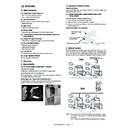
5. Breakdown sequence
A. Breakdown mode process
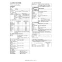
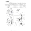
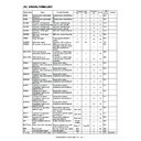
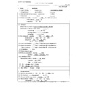
(1) Breakdown mode list
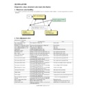
There are following cases of the breakdown mode.
∗
For FAX communication, refer to the sheet of “Call request and Call-
in.”
in.”
∗
The machine may be operated under some conditions.
∆
1: When detected except when in a job, the machine can be operated
in the OC mode.
∆
2: Can be operated except in the staple mode.
∆
3: When detected except in a job, the machine can be operated
except with the breakdown tray.
∆
4: Can be operated with some restriction on the image quality
depending on the destination. (Low density print) * Refer to the
process control trouble operation table below.
process control trouble operation table below.
∆
5: When detected except in a job, can be operated except in the trou-
ble paper exit section.
∆
6: When detected except in a job, can be operated in the single sur-
face scan mode.
∆
7: Can be operated except in the inserter tray, if the error is detected
in the standby mode.
∗
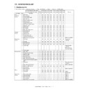
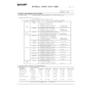
Process control trouble operation table
Judgment
block
Trouble code
Operation enable mode
(The machine can be operated under
some conditions.)
some conditions.)
Copy read
(including
interrupt)
FAX
send
Email
receive
FAX
print
Print
List
print
Notification
to
FASThost
(SPF breakdown)
Scanner
U5
∆
1
∆
1
∆
1
❍
❍
❍
❍
Scanner section breakdowns (Mirror
motor, lens, copy lamp)
motor, lens, copy lamp)
Scanner
L1, L3, U2 (80, 81)
✕
✕
✕
❍
❍
❍
❍
FAX board breakdown
MFP control/
FAX
F6, F7
❍
✕
❍
✕
❍
❍
✕
FAX power OFF
MFP control
❍
✕
❍
✕
❍
❍
✕
Network error
MFP control CE
❍
❍
✕
❍
❍
❍
✕
Staple breakdown
PCU
F1 (10)
∆
2
❍
❍
∆
2
∆
2
∆
2
❍
Paper feed tray breakdown
PCU
F3, U6 (LCC)
∆
3
❍
❍
∆
3
∆
3
∆
3
❍
(Process control breakdown)
PCU
F2 (31, 32, 37)
∆
4
❍
❍
∆
4
∆
4
∆
4
❍
PCU section breakdowns (Motor, fusing
section, etc.)
section, etc.)
PCU
C1, C2, C3, H2, H3, H4,
H5, L4 (excluding L4-30),
L8, U2 (90, 91), F2, F4
H5, L4 (excluding L4-30),
L8, U2 (90, 91), F2, F4
✕
❍
❍
✕
✕
✕
❍
After-process breakdown
PCU
F1
∆
5
❍
❍
∆
5
∆
5
∆
5
❍
Inserter trouble (excluding
communication trouble)
communication trouble)
PCU
F1 (61, 62)
∆
7
❍
❍
∆
7
∆
7
∆
7
❍
Laser breakdown
PCU
E7 (02 only), L6
✕
❍
❍
✕
✕
✕
❍
HDD breakdown
MFP control E7 (03)
✕
✕
✕
✕
✕
✕
❍
CCD breakdowns (Shading, etc.)
Scanner
E7 (10, 11, 12, 14)
✕
✕
✕
❍
❍
❍
❍
CIS breakdowns (Shading, etc.)
Scanner
E6 (10, 11, 14)
∆
6
∆
6
∆
6
❍
❍
❍
❍
Scanner communication trouble
MFP control E7 (80)
✕
✕
✕
❍
❍
❍
❍
PCU communication trouble
MFP control E7 (90)
✕
✕
✕
✕
✕
✕
❍
FAX backup battery voltage fall
MFP control U1 (01, 02)
❍
✕
✕
❍
❍
❍
❍
HDD registration data sum error
MFP control U2 (50)
❍
✕
✕
❍
❍
❍
❍
Thermistor trouble (trouble history)
PCU
F2 (39, 46, 47, 48)
❍
❍
❍
❍
❍
❍
❍
(The machine cannot be operated.)
Memory
MFP control U2 (00, 11, 12, 22, 23)
✕
✕
✕
✕
✕
✕
❍
External communication disable (RICA)
MFP control U7, PF
✕
✕
✕
✕
✕
✕
❍
Image memory trouble, decode error
MFP control E7 (01, 06)
✕
✕
✕
✕
✕
✕
❍
Incompatibility check error
MFP control/
PCU
E7 (50, 55, 56, 57, 60,
65, 66, 67)
65, 66, 67)
✕
✕
✕
✕
✕
✕
✕
Controller fan motor trouble
MFP control L4-30
✕
✕
✕
✕
✕
✕
✕
Trouble
code
Error content
Japan/SEC
Europe/
Others
F2-31
Process control sensor
gain adjustment failure
gain adjustment failure
Machine stop
Low density
copy
copy
F2-32
Mark detection failure
Low density
copy
copy
Low density
copy
copy
F2-37
Mark sensor gain
adjustment failure
adjustment failure
Machine stop
Low density
copy
copy
AR-M550/M620 SELF DIAG MESSAGE AND TROUBLESHOOTING 9 - 3
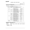
(2) Trouble mode process
The machine can be operated under some conditions.
Operations except for the trouble mode are enabled (READY). For the
modes which cannot be operated, only setting is enabled and a mes-
sage is given to show the operations are disabled. (NOT READY in this
case)
modes which cannot be operated, only setting is enabled and a mes-
sage is given to show the operations are disabled. (NOT READY in this
case)
(Display)
When a trouble occurs, a dialog is shown. In the mode where the oper-
ation is enabled, the OK button is added to the message. In the mode
where the operation is disabled, the OK button is not shown and the
display is kept until the trouble is canceled.
ation is enabled, the OK button is added to the message. In the mode
where the operation is disabled, the OK button is not shown and the
display is kept until the trouble is canceled.
(3) Writing to the trouble memory
In case of a same trouble in this machine, selection is made with the
simulation to write into the trouble memory or not. If this simulation is
set, any trouble is written into the trouble memory unconditionally.
simulation to write into the trouble memory or not. If this simulation is
set, any trouble is written into the trouble memory unconditionally.
(SIMULATION. 26-35)
0: A same trouble as the previous one is not written. (Default)
1: Any trouble is written into the trouble memory unconditionally.
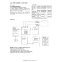
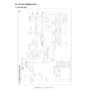
B. Power ON trouble detection sequence.
• When the power is turned ON, if H3, H4, H5, U1, U2, PF, L4-31, F3-12/22, or U6 (LCC-related sub code 09 only) is saved, a trouble code is imme-
diately displayed. E7 (50, 55, 56, 57, 60, 65, 66, 67) trouble is not saved.
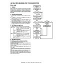
(Power ON sequence)
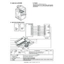
·
H3, H4, U1, U2, U6 PF trouble check
(To the corresponding block)
(Trouble cancel sequence)
·
When executing SIM 13, 14, 15, 16, 17
SIM 13: U1 trouble cancel
SIM 14: H3, H4, H5, L4-31 trouble cancel
SIM 15: LCC (U6), F3-12/22 trouble cancel
SIM 16: U2 trouble cancel
SIM 17: PF trouble cancel
SIM 14: H3, H4, H5, L4-31 trouble cancel
SIM 15: LCC (U6), F3-12/22 trouble cancel
SIM 16: U2 trouble cancel
SIM 17: PF trouble cancel
ICU event
manager
Communication of trouble status
[Trouble data ID] [Trouble code]
[Trouble data ID] [Trouble code]
sim task
Trouble cancel command
Trouble cancel status is
communicated.
communicated.
Each block
When the power is turned on,
check is made in each block.
check is made in each block.
Trouble cancel
(The trouble memory is
initialized.)
(The trouble memory is
initialized.)
Trouble check is made in each block when initializing
and data are sent to the ICU.
H3, H4, H5, L4-31, F3-12/22: Saved in the PCU.
U1: Saved in the ICU.
U2: Saved in each block.
PF: Saved in the ICU.
U6-09: Saved in the PCU.
and data are sent to the ICU.
H3, H4, H5, L4-31, F3-12/22: Saved in the PCU.
U1: Saved in the ICU.
U2: Saved in each block.
PF: Saved in the ICU.
U6-09: Saved in the PCU.
AR-M550/M620 SELF DIAG MESSAGE AND TROUBLESHOOTING 9 - 4
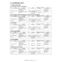
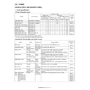
6. Communication in trouble
A. FAX call request/call-in specifications
∆
2: Enable except for the trouble tray
∗
When, however, a paper feed tray trouble is detected during a job, the engine is stopped and printing is disabled.
∆
3: The display goes to the FAX status check menu and the list can be printed.: The received document is outputted.
∆
4: Paper exit is enabled except for the trouble paper exit tray
∗
When, however, a paper feed tray trouble is detected during a job, the engine is stopped and printing is disabled.
7. Trouble kind
Trouble
Send
reservation
Print
Call
request
Call-in
Precaution
PCU breakdowns (Incompatibility check error: E7 (50, 56, 57,
65, 66, 67))
65, 66, 67))
❍
×
❍
Note
There is a risk that the memory is full.
F3, U6 (Paper feed tray breakdown)
❍
∆
2
❍
❍
F1 (Paper exit section breakdown)
❍
∆
4
❍
❍
Scanner breakdowns
×
❍
❍
❍
F6, F7 (FAX breakdown)
×
×
×
×
E7 (01, 06) (MFP control breakdown)
×
×
×
×
U2 (00, 11, 12, 22, 23, 50) (MFP control memory error)
×
×
×
×
U7 (RIC external communication disable), PF
×
×
×
×
Inhibition of use by a customer having
outstanding fee
outstanding fee
U1 (Backup battery voltage fall)
×
∆
3
× Note
×
Transfer enable
E7 (50, 55, 56, 57, 60, 65, 66, 67) (Incompatibility check error)
×
×
×
×
L4-30 (Controller fan motor trouble)
×
×
×
×
Door open
❍
×
❍
❍
Note
There is a risk that the memory is full.
Toner empty
❍
×
❍
❍
Note
There is a risk that the memory is full.
Process cartridge uninstalled, etc.
❍
×
❍
❍
Note
There is a risk that the memory is full.
Paper empty
❍
×
❍
❍
Note
There is a risk that the memory is full.
Paper JAM
❍
×
❍
❍
Note
There is a risk that the memory is full.
Document JAM
×
❍
❍
❍
Simulation
×
×
×
×
Key operation (Communication disable)
×
×
×
×
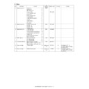
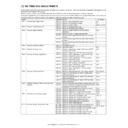
Trouble code
Trouble content
Remarks
Trouble
detection
Mechanism
Option Electricity FAX Supply
Main
code
code
Sub
code
C1
00
MC trouble
PCU
●
CE
00
Another communication error occurs.
Network
CE
01
The network card is not installed or broken.
Network
CE
02
The specified mail server or the FTP server is not
found.
found.
Network
CE
03
The specified server suspends response during
transmission of images.
transmission of images.
Network
CE
04
The entered account name of the FTP server or
the password for authentication is invalid.
the password for authentication is invalid.
Network
CE
05
The entered directory of the FTP server is invalid.
Network
CE
06
The specified mail server (POP3) is not found.
Network
CE
07
The entered account name of the POP3 server or
the password for authentication is invalid.
the password for authentication is invalid.
Network
CE
08
The specified mail server (POP3) suspends
response.
response.
Network
CH
–
Door open (CH ON)
PCU
E6
11
CIS shading trouble (White correction)
Scanner
●
E6
14
CIS-ASIC communication trouble
Scanner
●
E7
01
System data trouble
MFP control
–
–
–
–
–
E7
02
Laser trouble
PCU
●
E7
03
HDD trouble
MFP control
●
E7
06
Decode error trouble
MFP control
●
E7
10
CCD shading trouble (Black correction)
Scanner
●
E7
11
CCD shading trouble (White correction)
Scanner
●
E7
12
CCD shading trouble (White correction center
adjustment)
adjustment)
Scanner
●
E7
14
CCD-ASIC communication trouble
Scanner
●
E7
50
LSU connection trouble
PCU
●
E7
55
Incompatibility check (Engine (PCU) detection)
PCU
●
AR-M550/M620 SELF DIAG MESSAGE AND TROUBLESHOOTING 9 - 5
E7
56
Incompatibility check (Engine (PCU) detection)
PCU
●
E7
57
Incompatibility check (Engine (PCU) detection)
PCU
●
E7
60
Controller connection trouble
MFP control
●
E7
65
Incompatibility check (MFP controller detection)
MFP control
●
E7
66
Incompatibility check (MFP controller detection)
MFP control
●
E7
67
Incompatibility check (MFP controller detection)
MFP control
●
E7
80
Scanner PWB communication trouble
MFP control
●
E7
90
PCU PWB communication trouble
MFP control
●
EE
EL
Auto developer adjustment trouble (Overtoner
error)
error)
During SIM only
PCU
●
EE
EU
Auto developer adjustment trouble (Undertoner
error)
error)
During SIM only
PCU
●
F1
00
Finisher communication trouble
PCU
●
F1
02
Finisher transport motor abnormality
PCU
●
F1
03
Finisher oscillation motor trouble
PCU
●
F1
08
Finisher staple shift motor trouble
PCU
●
F1
09
Finisher load capacity sensor trouble
PCU
●
F1
10
Finisher/staple motor trouble
PCU
●
F1
11
Finisher/pusher motor trouble
PCU
●
F1
15
Finisher elevator motor trouble
PCU
●
F1
19
Finisher/jogger motor trouble
PCU
●
F1
31
Finisher saddle folding motor trouble
PCU
●
F1
32
Finisher-saddle communication trouble
PCU
●
F1
33
Finisher/punch shift motor trouble
PCU
●
F1
34
Finisher/punch motor trouble
PCU
●
F1
37
Finisher/backup RAM data trouble
PCU
●
F1
38
Finisher/punch backup RAM data trouble
PCU
●
F1
41
Finisher/saddle positioning plate motor trouble
PCU
●
F1
42
Finisher/saddle guide motor trouble
PCU
●
F1
43
Finisher/saddle alignment motor trouble
PCU
●
F1
44
Finisher/saddle rear staple motor trouble
PCU
●
F1
45
Finisher/saddle front staple motor trouble
PCU
●
F1
46
Finisher/saddle push motor trouble
PCU
●
F1
51
Finisher/sensor connector connection trouble
PCU
●
F1
52
Finisher/micro switch trouble
PCU
●
F1
60
Finisher-inserter communication trouble
PCU
●
F1
61
Inserter/EEPROM trouble
PCU
●
F1
62
Inserter/reverse sensor trouble
PCU
●
F2
00
Toner concentration sensor open
PCU
●
F2
02
Toner supply abnormality
PCU
●
F2
04
Improper cartridge (Destination error, life cycle
error)
error)
PCU
●
F2
05
CRUM error
PCU
●
F2
31
Process control trouble (Photoconductor surface
reflection rate abnormality)
reflection rate abnormality)
PCU
●
F2
32
Process control trouble (Drum marking scan
failure)
failure)
PCU
●
F2
37
Drum marking sensor gain adjustment error
PCU
●
F2
39
Process thermistor breakdown
PCU
●
F2
46
Developing thermistor breakdown
PCU
●
F2
47
Room temperature thermistor breakdown
PCU
●
F2
48
Developing humidity sensor break down
PCU
●
F3
12
Tray 1 lift-up trouble
PCU
●
F3
22
Tray 2 lift-up trouble
PCU
●
F3
32
Tray 3 lift-up trouble
PCU
●
F3
42
Tray 4 lift-up trouble
PCU
●
F4
38
38 (V) voltage trouble
PCU
●
F6
00
FAX board communication trouble
MFP control
●
F6
01
FAX expansion flash ROM abnormality
MFP control
●
F6
04
FAX modem operation abnormality
FAX
●
F6
20
FAX write protect cancel
FAX
●
F6
21
Combination error of TEL/LIU PWB and software
FAX
●
Trouble code
Trouble content
Remarks
Trouble
detection
Mechanism
Option Electricity FAX Supply
Main
code
code
Sub
code

