|
|
AR-M550 (serv.man4)
ALL DATA
Service Manual
|
127
|
50.95 MB
|
|
|
AR-M550 (serv.man5)
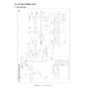
CIRCUIT DIAGRAM
Service Manual
|
127
|
17.27 MB
|
|
|
AR-M550 (serv.man6)
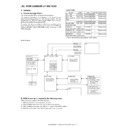
(1) Outline
Service Manual
|
3
|
338.61 KB
|
|
|
AR-M550 (serv.man7)
(2) Configuration
Service Manual
|
2
|
72.45 KB
|
|
|
AR-M550 (serv.man8)
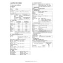
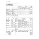
(3) Specifications
Service Manual
|
16
|
215.92 KB
|
|
|
AR-M550 (serv.man9)
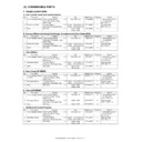
(4) Consumable parts
Service Manual
|
4
|
43.79 KB
|
|
|
AR-M550 (serv.man10)
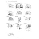
(5) External view and internal structure
Service Manual
|
25
|
1.74 MB
|
|
|
AR-M550 (serv.man11)
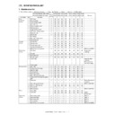
(6a) List of sections, Operation panel section, Paper feed transport duplex exit revserse sections.
Service Manual
|
59
|
14.16 MB
|
|
|
AR-M550 (serv.man12)
(6b) Laser scan unit, Image process section, Scanner section, Fusing section, SPF section
Service Manual
|
71
|
13.91 MB
|
|
|
AR-M550 (serv.man13)
(6c) Drive section, Filters, PWB section, Power section, Fan motors, Sensors and Switches
Service Manual
|
26
|
7.63 MB
|
|
|
AR-M550 (serv.man15)
(8) Simulation
Service Manual
|
98
|
905.4 KB
|
|
|
AR-M550 (serv.man16)
(9) Self diag message and troubleshooting
Service Manual
|
47
|
814.54 KB
|
|
|
AR-M550 (serv.man17)
(10) ROM version-up method
Service Manual
|
6
|
263.95 KB
|
|
|
AR-M550 (serv.man18)
(11) Maintenance list
Service Manual
|
14
|
1.56 MB
|
|
|
AR-M550 (serv.man19)
(12) Other
Service Manual
|
8
|
589.03 KB
|
|
|
AR-M550 (serv.man20)
(13) Actual wiring chart
Service Manual
|
15
|
322.62 KB
|
|
|
AR-M550 (serv.man21)
(14) Signal name list
Service Manual
|
15
|
487.02 KB
|
|
|
AR-M550 (serv.man22)
ARM550 620 Circuit Diagrams
Service Manual
|
127
|
17.06 MB
|
|
|
AR-M550 (serv.man23)
ARM550 620 Installation Manual
Service Manual
|
56
|
7.48 MB
|
|
|
AR-M550 (serv.man28)
ARM550 620-Operation Manual (Copy)
User Manual / Operation Manual
|
127
|
5.25 MB
|
|
|
AR-M550 (serv.man29)
ARM550 620-Key Operators Guide
User Manual / Operation Manual
|
20
|
493.04 KB
|

|
AR-M550
ARM550 620 700 Mac PPD for MacOS 10.1, 10.2, 10.3, 10.4, 10.5 and 10.6. Mac OS
Drivers
|
|
6.62 MB
|

|
AR-M550 (serv.man150)
ARM236 256 276 316 351 451 550 620 700 PS Driver for Windows Vista 64Bit. Version 801a WHQL signed. Windows Vista
Drivers
|
|
10.76 MB
|

|
AR-M550 (serv.man151)
Windows Vista PCL6 64 Bit Driver. Windows Vista
Drivers
|
|
5.86 MB
|

|
AR-M550 (serv.man152)
Windows Vista PCL6 Driver. This diver can be used in conjunction with 64 Bit printer driver. Windows Vista
Drivers
|
|
5.17 MB
|

|
AR-M550 (serv.man153)
Windows 2000 PCL6 64 Bit Driver. Windows 2000
Drivers
|
|
5.86 MB
|

|
AR-M550 (serv.man154)
Windows 2000 PCL6 Driver. This diver can be used in conjunction with 64 Bit printer driver. Windows 2000
Drivers
|
|
5.17 MB
|

|
AR-M550 (serv.man155)
ARM236 256 276 316 351 451 550 620 700 PS Driver for Windows XP 64Bit. Version 801a WHQL signed. Windows XP
Drivers
|
|
10.76 MB
|

|
AR-M550 (serv.man156)
Windows XP PCL6 64 Bit Driver. Windows XP
Drivers
|
|
5.86 MB
|

|
AR-M550 (serv.man157)
Windows XP PCL6 Driver. This diver can be used in conjunction with 64 Bit printer driver. Windows XP
Drivers
|
|
5.17 MB
|
|
|
AR-M550 (serv.man24)
ARM550 620 700 Parts Guide (Revised March 2011)
Service Manual / Parts Guide
|
127
|
15.66 MB
|
|
|
AR-M550 (serv.man25)
ARM550 620 700 Parts Guide (Revised)
Service Manual / Parts Guide
|
127
|
17.99 MB
|
|
|
AR-M550 (serv.man26)
Complete Parts Guide.
Service Manual / Parts Guide
|
127
|
15.54 MB
|
|
|
AR-M550 (serv.man27)
Part Guide for ARM550 620 700 PWB's
Service Manual / Parts Guide
|
37
|
565.97 KB
|

|
AR-M550 (serv.man3)
ARM550 620 700 BERTL Test reports and Certificates
Service Manual / Specification
|
|
4.35 MB
|
|
|
AR-M550 (serv.man62)
Reinforcement of the Delivery Actuator
Service Manual / Technical Bulletin
|
2
|
271.3 KB
|
|
|
AR-M550 (serv.man63)
ARE-1085 Modified waste toner transfer pipe due to Leakage.
Service Manual / Technical Bulletin
|
2
|
108.21 KB
|
|
|
AR-M550 (serv.man64)
ARE1010 REMOVAL OF SCREWS FROM THE DUCT AND REAR FRAME 2 3.
Service Manual / Technical Bulletin
|
2
|
407.03 KB
|
|
|
AR-M550 (serv.man65)
REF ARE 1002 PREVENTION OF THE MANUAL PAPER FEED UNIT SEPARATION TORQUE LIMITER COMING LOOSE.
Service Manual / Technical Bulletin
|
2
|
182.34 KB
|
|
|
AR-M550 (serv.man66)
ARE 991 DAMAGE TO THE 1ST 2ND PAPER FEED DRIVE UNIT AND THE DRUM DRIVE UNIT SHAFTS.
Service Manual / Technical Bulletin
|
3
|
576.33 KB
|
|
|
AR-M550 (serv.man67)
Ref ARE 984 IMAGE TROUBLE (WHITE STREAKS) CAUSED BY GRINDING DOWN OF THE DRUM.
Service Manual / Technical Bulletin
|
2
|
597.25 KB
|
|
|
AR-M550 (serv.man68)
Ref CCE779 AR-CF2 COUNTERMEASURES FOR JAM (HI_SEN_S, ETC.)RESULTING FROM MISALIGNED SPRING HOOK SECTION OF DELIVERY SENSOR LEVER.
Service Manual / Technical Bulletin
|
2
|
342.03 KB
|
|
|
AR-M550 (serv.man69)
Ref ARE971 MX-F16 NEW SERVICE PARTS FOR THE SADDLE-STITCH FINISHER EJECTION TRAYS
Service Manual / Technical Bulletin
|
6
|
2.24 MB
|
|
|
AR-M550 (serv.man70)
ARE-969 IMPROVEMENT BY REMOVING THE SHAFT BEARINGS OF THE PS ROLLER REAR SIDE.
Service Manual / Technical Bulletin
|
2
|
154.15 KB
|
|
|
AR-M550 (serv.man71)
ARE-962 F1-46 TROUBLE CODE OCCURRENCE AFTER JAM PROCESSING.
Service Manual / Technical Bulletin
|
2
|
290.02 KB
|
|
|
AR-M550 (serv.man72)
REF ARE960 PRECAUTIONS WHEN REPLACING THE DV SIDE SEAL
Service Manual / Technical Bulletin
|
3
|
1.26 MB
|
|
|
AR-M550 (serv.man73)
ARE-956 IMPROVEMENTS MADE TO THE PROCESS UNIT AGAINST TONER SPLASHING ON THE SUB-BLADE
Service Manual / Technical Bulletin
|
3
|
1.26 MB
|
|
|
AR-M550 (serv.man74)
REF ARE-947 SUB-HEATER CLEANING FELT PLATE CHANGE, TO PREVENT PEALING OF THE FELT FROM PLATE.
Service Manual / Technical Bulletin
|
2
|
270.86 KB
|
|
|
AR-M550 (serv.man75)
REF ARE-945 ALTERATION TO THE MANUAL PAPER FEED BASE TO PREVENT DAMAGE TO THE BOSS.
Service Manual / Technical Bulletin
|
2
|
245.2 KB
|
|
|
AR-M550 (serv.man76)
ARE936 IMPROVEMENT AGAINST TONER SPLATTERING FROM UNDER THE SUB BLADE.
Service Manual / Technical Bulletin
|
2
|
355.35 KB
|
|
|
AR-M550 (serv.man77)
CCE694 CHANGE OF INITIAL VALUES OF PREHEAT MODE AND AUTO POWER SHUT-OFF MODE INVOLVED IN SUPPORT OF ENERGY STAR VER1.1 (TIER II).
Service Manual / Technical Bulletin
|
1
|
22.91 KB
|
|
|
AR-M550 (serv.man78)
ARE916 IMPROVEMENT IN PAPER FEEDING PERFOMANCE OF SPF.
Service Manual / Technical Bulletin
|
2
|
94.05 KB
|
|
|
AR-M550 (serv.man79)
AER900 COUNTER MEASURE AGAINST REVERSE PRESSURE RELEASE LEVER COMING AWAY FROM ITS HOOK.
Service Manual / Technical Bulletin
|
1
|
106.88 KB
|
|
|
AR-M550 (serv.man80)
ARE-891R NEW SETUP PROCEDURE WHEN REPLACING DEVELOPER (SUPERSEDING BULLETIN DATED 1ST JULY 2008)
Service Manual / Technical Bulletin
|
1
|
69.32 KB
|
|
|
AR-M550 (serv.man81)
ARE 896. AR-F15 F16 ROM upgrade.
Service Manual / Technical Bulletin
|
1
|
27.39 KB
|
|
|
AR-M550 (serv.man82)
ARE 897. AR-F16 Saddle unit ROM UPGRADE
Service Manual / Technical Bulletin
|
1
|
25.71 KB
|
|
|
AR-M550 (serv.man83)
ENHANCEMENT OF STRENGTH OF DSPF (SPF) ADJUST PLATES F R.
Service Manual / Technical Bulletin
|
2
|
409.12 KB
|
|
|
AR-M550 (serv.man84)
ARE888 TONER CARTRIDGE NOT FITTING CORRECTLY, DUE TO THE TONER HOPPER CONNECTOR PLATE DEFORMING.
Service Manual / Technical Bulletin
|
2
|
285.57 KB
|
|
|
AR-M550 (serv.man85)
ARE 891. CHANGE TO THE TONER DENSITY REFERENCE SETUP PROCEDURE IN THE INSTALLATION MANUAL.
Service Manual / Technical Bulletin
|
2
|
171.43 KB
|
|
|
AR-M550 (serv.man86)
ARE882-F2-00 ETC. DUE TO POOR CONTACT BETWEEN TRANSFER AC TERMINAL AND TRANSFER ELECTRODE SPRING.
Service Manual / Technical Bulletin
|
2
|
343.86 KB
|
|
|
AR-M550 (serv.man87)
Counter Measures Taken When Copy lamp Is Not Switched On Due To Glass Being Charged
Service Manual / Technical Bulletin
|
2
|
85.72 KB
|
|
|
AR-M550 (serv.man88)
Strength Improvement Of The Output Axis Gear Of The Lift Motor A
Service Manual / Technical Bulletin
|
2
|
75.64 KB
|
|
|
AR-M550 (serv.man89)
ROM Version Update (17) Please See Bulletin For Details
Service Manual / Technical Bulletin
|
5
|
28.46 KB
|
|
|
AR-M550 (serv.man90)
Improvement Of The Fusing Unit
Service Manual / Technical Bulletin
|
6
|
169.37 KB
|

|
AR-M550 (serv.man91)
Improvment in initial low Density, Halftone density and such
Service Manual / Technical Bulletin
|
|
122.99 KB
|
|
|
AR-M550 (serv.man92)
LIFT UP MOTOR FAILURES ARE816
Service Manual / Technical Bulletin
|
2
|
229.08 KB
|
|
|
AR-M550 (serv.man93)
Part change information to fuser unit.
Service Manual / Technical Bulletin
|
3
|
163.25 KB
|
|
|
AR-M550 (serv.man94)
053 ROM Version 15
Service Manual / Technical Bulletin
|
2
|
65.87 KB
|
|
|
AR-M550 (serv.man95)
052-Change to new type flash ROM (ELEM)
Service Manual / Technical Bulletin
|
2
|
140.44 KB
|
|
|
AR-M550 (serv.man96)
051-Making LCD, FFC and LVDS INV board service parts available as a kit.
Service Manual / Technical Bulletin
|
2
|
58.14 KB
|
|
|
AR-M550 (serv.man97)
Improvement of the fusing unit.
Service Manual / Technical Bulletin
|
3
|
183.54 KB
|
|
|
AR-M550 (serv.man98)
Update to tech bulletins 048 (ARM550U M620U), 030 (ARM700U). Improvement for initial low density and halftone density.
Service Manual / Technical Bulletin
|
1
|
107.7 KB
|
|
|
AR-M550 (serv.man99)
Improvement for initial low density and halftone density.
Service Manual / Technical Bulletin
|
2
|
112.88 KB
|
|
|
AR-M550 (serv.man100)
046. ROM upgrade
Service Manual / Technical Bulletin
|
2
|
104.1 KB
|
|
|
AR-M550 (serv.man101)
Measures to prevent double feeding and noise from tandem sheet feeder.
Service Manual / Technical Bulletin
|
2
|
50.9 KB
|
|
|
AR-M550 (serv.man102)
Change in I F connectors for coin vendors.
Service Manual / Technical Bulletin
|
1
|
25.38 KB
|
|
|
AR-M550 (serv.man103)
ROM Upgrade..12
Service Manual / Technical Bulletin
|
3
|
12.56 KB
|
|
|
AR-M550 (serv.man104)
Additions to details described in simulation 62-10.
Service Manual / Technical Bulletin
|
1
|
36.84 KB
|
|
|
AR-M550 (serv.man105)
Measures against noise generated from the toner motor on the toner cartridge.
Service Manual / Technical Bulletin
|
3
|
40.16 KB
|
|
|
AR-M550 (serv.man106)
Improvement in halftone image quality.
Service Manual / Technical Bulletin
|
6
|
1.53 MB
|
|
|
AR-M550 (serv.man107)
To reduce paper skew or paper misfeeding when duplex copying printing.
Service Manual / Technical Bulletin
|
2
|
104.81 KB
|
|
|
AR-M550 (serv.man108)
Prevention of thermistor marks appearing on the upper fuser roller.
Service Manual / Technical Bulletin
|
1
|
18.02 KB
|
|
|
AR-M550 (serv.man109)
Prevention of the paper discharge actuator becoming detached.
Service Manual / Technical Bulletin
|
1
|
25.17 KB
|
|
|
AR-M550 (serv.man110)
Improvement to clear waste toner from the process unit.
Service Manual / Technical Bulletin
|
6
|
1.69 MB
|
|
|
AR-M550 (serv.man111)
Performane enhancemwnts with ROM upgrade 10..v4.00
Service Manual / Technical Bulletin
|
31
|
2.85 MB
|
|
|
AR-M550 (serv.man112)
Remedy for U2-50 error that occurs when a security kit is installed.
Service Manual / Technical Bulletin
|
3
|
187.32 KB
|
|
|
AR-M550 (serv.man113)
032-Increased margins of detection for MPRD2 sensor in the interface pass unit.
Service Manual / Technical Bulletin
|
2
|
44.51 KB
|
|
|
AR-M550 (serv.man114)
034-Increase adhesion strength of the oil roller to the core shaft.
Service Manual / Technical Bulletin
|
2
|
49.67 KB
|
|
|
AR-M550 (serv.man115)
033-Rom upgrade 10
Service Manual / Technical Bulletin
|
2
|
48.13 KB
|
|
|
AR-M550 (serv.man116)
031-Measures against misfeeding at POD1_N, due to breaking chipping of the upper fuser pawls and the drum pick off pawls.
Service Manual / Technical Bulletin
|
8
|
339.86 KB
|
|
|
AR-M550 (serv.man117)
030-Discontinued use of the one-way gear (30T) in the left-hand door unit.
Service Manual / Technical Bulletin
|
2
|
101.36 KB
|
|
|
AR-M550 (serv.man118)
029-Improvement to prevent the deformation of the door switch lever.
Service Manual / Technical Bulletin
|
1
|
20.82 KB
|
|
|
AR-M550 (serv.man119)
028-Change of side seal R on the processing unit.
Service Manual / Technical Bulletin
|
1
|
60.63 KB
|
|
|
AR-M550 (serv.man120)
027-Prevention against indicating incorrect paper size on the manual paper feed tray.
Service Manual / Technical Bulletin
|
2
|
45.47 KB
|
|
|
AR-M550 (serv.man121)
026-To prevent an abnormal noise generated from the waste toner transport idle gear.
Service Manual / Technical Bulletin
|
1
|
48.98 KB
|
|
|
AR-M550 (serv.man122)
025-Prevention of POD1_N misfeeds due to the paper being caught on the broken upper separator pawl of the fusing unit.
Service Manual / Technical Bulletin
|
1
|
42.72 KB
|
|
|
AR-M550 (serv.man123)
024-Improvement for the white void of the second side when a thin paper document is duplexed using the SPF.
Service Manual / Technical Bulletin
|
1
|
42.17 KB
|
|
|
AR-M550 (serv.man124)
023-Prevention of POD1_N misfeeds due to the paper caught on the drum separator pawl section.
Service Manual / Technical Bulletin
|
4
|
225.7 KB
|
|
|
AR-M550 (serv.man125)
022-Adjustment required when replacing the CIS unit or the CIS pwb is replaced.
Service Manual / Technical Bulletin
|
1
|
8.36 KB
|
|
|
AR-M550 (serv.man126)
020-Improvement made to prevent rib of first second paper feed (tandem paper feed) from being broken.
Service Manual / Technical Bulletin
|
2
|
110.23 KB
|
|
|
AR-M550 (serv.man127)
021-To prevent blurr sections at the end of an A3 copy.
Service Manual / Technical Bulletin
|
1
|
7.49 KB
|
|
|
AR-M550 (serv.man128)
019-Improvement of the reset ability of the conveyance sensors for the fifth tray interface and the manual bypass feeder.
Service Manual / Technical Bulletin
|
2
|
37.14 KB
|
|
|
AR-M550 (serv.man129)
018-Change in the MC cleaner handle.
Service Manual / Technical Bulletin
|
2
|
90.33 KB
|
|
|
AR-M550 (serv.man130)
017-H4-02 Trouble
Service Manual / Technical Bulletin
|
2
|
68.03 KB
|
|
|
AR-M550 (serv.man131)
016-To enhance reliability of the fuser unit pressure roller in line with the ARM700
Service Manual / Technical Bulletin
|
6
|
478.63 KB
|
|
|
AR-M550 (serv.man132)
Improvement on the deformating of door switch lever
Service Manual / Technical Bulletin
|
1
|
86.89 KB
|
|
|
AR-M550 (serv.man133)
ROM Upgrade .7
Service Manual / Technical Bulletin
|
2
|
35.6 KB
|
|
|
AR-M550 (serv.man134)
Change of shape of jam release junction shaft in output paper section
Service Manual / Technical Bulletin
|
1
|
89.5 KB
|
|
|
AR-M550 (serv.man135)
Change of first second paper feeder PG upper part
Service Manual / Technical Bulletin
|
1
|
96.71 KB
|
|
|
AR-M550 (serv.man136)
Change of intake mechanism drive shaft in manual
Service Manual / Technical Bulletin
|
1
|
73.36 KB
|
|
|
AR-M550 (serv.man137)
Change of paper detection actuator and separation roller cover in manual paper feeder units
Service Manual / Technical Bulletin
|
2
|
95 KB
|
|
|
AR-M550 (serv.man138)
Addition of INT SP harness in rear frame section
Service Manual / Technical Bulletin
|
1
|
128.78 KB
|
|
|
AR-M550 (serv.man139)
Change of side seals in process unit
Service Manual / Technical Bulletin
|
1
|
111.8 KB
|
|
|
AR-M550 (serv.man140)
Stay for the fixing section has been changed, and the auxiliary CL roller SP has been added.
Service Manual / Technical Bulletin
|
1
|
92.04 KB
|
|
|
AR-M550 (serv.man141)
Irregular sound caused by Tandem Cover Unit
Service Manual / Technical Bulletin
|
2
|
147.68 KB
|
|
|
AR-M550 (serv.man142)
Dragon fuser mod kit, please refer to Technical Bulletin 016 for further details.
Service Manual / Technical Bulletin
|
4
|
77.18 KB
|
|
|
AR-M550 (serv.man143)
Upgrading of ROM version (6)
Service Manual / Technical Bulletin
|
4
|
393.36 KB
|
|
|
AR-M550 (serv.man144)
Correction for DC power blowout due to contact of EMI filter and CIS cover
Service Manual / Technical Bulletin
|
2
|
188.89 KB
|
|
|
AR-M550 (serv.man145)
Additional work for replacing photoconductive drum
Service Manual / Technical Bulletin
|
1
|
39.68 KB
|
|
|
AR-M550 (serv.man146)
ROM upgrade .. (4), (5)
Service Manual / Technical Bulletin
|
3
|
39.58 KB
|

|
AR-M550 (serv.man32)
REF. ARE932 Energy Star ROM UPGRADE ... (18). WITH AR-P19 NON-ELEM
Driver / Update
|
|
222.52 KB
|

|
AR-M550 (serv.man33)
REF. ARE932 Energy Star ROM UPGRADE ... (18). WITH AR-P19 ELEM
Driver / Update
|
|
197.12 KB
|

|
AR-M550 (serv.man34)
REF. ARE932 Energy Star ROM UPGRADE ... (18). WITHOUT AR-P19 ELEM
Driver / Update
|
|
9.72 MB
|

|
AR-M550 (serv.man35)
REF. ARE932 Energy Star ROM UPGRADE ... (18). WITHOUT AR-P19 NON-ELEM
Driver / Update
|
|
9.72 MB
|

|
AR-M550 (serv.man36)
ARM550 620 700 OSA Firmware V5.d51 ELEM
Driver / Update
|
|
12.82 MB
|

|
AR-M550 (serv.man37)
ARM550 620 700 OSA Firmware V5.d51 Non ELEM
Driver / Update
|
|
12.81 MB
|

|
AR-M550 (serv.man38)
P19 Firmware Update For 'U' Version Models Vp4.05
Driver / Update
|
|
13.14 MB
|

|
AR-M550 (serv.man39)
P19 Firmware Update For 'U' Version Models (ELEM) Vp4.05
Driver / Update
|
|
13.15 MB
|

|
AR-M550 (serv.man40)
Firmware Update For 'U' Version Models Vu4.05
Driver / Update
|
|
10.61 MB
|

|
AR-M550 (serv.man41)
Firmware Update For 'U' Version Models (ELEM) Vu4.05
Driver / Update
|
|
10.62 MB
|

|
AR-M550 (serv.man42)
DSK Firmware October 2007
Driver / Update
|
|
13.38 MB
|

|
AR-M550 (serv.man43)
DSK Firmware October 2007 (ELEM)
Driver / Update
|
|
13.38 MB
|

|
AR-M550 (serv.man44)
Non-Elem type firmware. u4a.04
Driver / Update
|
|
10.72 MB
|

|
AR-M550 (serv.man45)
ARM550 620 700 OSA Firmware V5.51 Non ELEM
Driver / Update
|
|
13.72 MB
|

|
AR-M550 (serv.man46)
ARM550 620 700 OSA Firmware V5.51 ELEM
Driver / Update
|
|
13.73 MB
|

|
AR-M550 (serv.man47)
Firmware Oct 2006 Elem with P19
Driver / Update
|
|
13.13 MB
|

|
AR-M550 (serv.man48)
Firmware Oct 2006 Non Elem with P19
Driver / Update
|
|
13.13 MB
|

|
AR-M550 (serv.man49)
Firmware Update Oct 2006 elem Models
Driver / Update
|
|
13.13 MB
|

|
AR-M550 (serv.man50)
Firmware Update Oct 2006 Non elem Models
Driver / Update
|
|
13.13 MB
|

|
AR-M550 (serv.man51)
For U version models fitted with AR-P19 - Elem type firmware.(Main up to Vp4.04, Boot up to VM5.33A, PCU up to V03.11. Upgrade Utility and change details enclosed.
Driver / Update
|
|
13.31 MB
|

|
AR-M550 (serv.man52)
For U version models fitted with AR-P19 - Non-Elem type firmware.(Main up to Vp4.04, Boot up to VM5.33A, PCU up to V03.11. Upgrade Utility and change details enclosed.
Driver / Update
|
|
13.3 MB
|

|
AR-M550 (serv.man53)
For U version models (no P19 fitted) - Elem type firmware. (Main up to Vu4.04, Boot up to VM5.33A, PCU up to V03.11. Change details enclosed.
Driver / Update
|
|
10.78 MB
|

|
AR-M550 (serv.man54)
For U version models (no P19 fitted) - Non-Elem type firmware.(Main up to Vu4.04, Boot up to VM5.33A, PCU up to V03.11. Change details enclosed.
Driver / Update
|
|
10.77 MB
|

|
AR-M550 (serv.man55)
Common PC Fax Driver (v2.3.0.110) for Andromeda, Pegasus E, Tiger, Jupiter and Dragon Products.
Driver / Update
|
|
16.61 MB
|

|
AR-M550 (serv.man56)
ARM550 M620 M700 P19 firmware, ROM control F01 V4p.03, includes updated PCU (v03.10) and SCN (v02.10) for machine installed with ARP19. Improvement of initial low density and halftone density. Please read tech bulletins 048 and 049 (ARM550 M620), 030 and 031 (ARM700) or 007 (ARP19) for more details.
Driver / Update
|
|
13.09 MB
|

|
AR-M550 (serv.man57)
ARM550 M620 M700 firmware, ROM control no. F01 Vu4.03, includes updated PCU (v03.10) and SCN (v02.10), only for 'U'version machines. Improvement of initial low denity and halftone density. Please read tech bulletins 048 (ARM550 M620) or 030 (ARM700) for more details.
Driver / Update
|
|
10.56 MB
|

|
AR-M550 (serv.man58)
ARM550 620 700U firmware vp4a.03 when an ARP19 is installed, compatible for halftone image quality and Batch Printing.
Driver / Update
|
|
13.22 MB
|

|
AR-M550 (serv.man59)
ARM550 620 700U firmware vp4.03 when an ARP19 is installed, compatible for halftone image quality.
Driver / Update
|
|
13.2 MB
|

|
AR-M550 (serv.man60)
ARM550 620 700U firmware vu4.03 when an ARP19 is NOT installed, compatible for halftone image quality.
Driver / Update
|
|
10.67 MB
|

|
AR-M550 (serv.man61)
ARM550 ARM620 ARM700 Firmware Update Tool.
Driver / Update
|
|
113.84 KB
|
|
|
AR-M550 (serv.man2)
Handy Guide ARM550 620 700 Feb2005
Handy Guide
|
48
|
535.54 KB
|
|
|
AR-M550 (serv.man30)
Commands for selection of paper input and output trays. Including Escape codes, PJL commands and Postscript commands.
FAQ
|
66
|
274.11 KB
|

|
AR-M550 (serv.man31)
Aid to help fault find paper misfeeds. This flash animation describes paper feed sections in all units, main body, ARF16, ARCF2, ARLC6.
FAQ
|
|
1.89 MB
|
|
|
AR-M550 (serv.man147)
ARM550 Safety Sheet
Regulatory Data
|
2
|
44.61 KB
|
|
|
AR-M550 (serv.man148)
ARM550 MSDS sheet
Regulatory Data
|
4
|
29.23 KB
|
|
|
AR-M550 (serv.man149)
AR620ND_DV MSDS (F-31221)
Regulatory Data
|
4
|
29.19 KB
|

