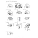
Sharp AR-M550 (serv.man11) Service Manual ▷ View online
AR-M550/M620 DETAILS OF EACH SECTION 6 - 45
C. Maintenance and parts replacement
(1) Maintenance list
✕
: Check (Clean, replace, or adjust as necessary.)
❍
: Clean
▲
: Replace
∆
: Adjust
✩
: Lubricate
❏
: Shift position
Code
Signal
name
Name
Function/Operation
Type
Model
Note
POD1
POD1
Paper exit detector 1
Paper exit detection from fusing
Transmission
type
type
Paper transport system
sensor
sensor
POD2
POD2
Paper exit detector 2
Paper pass detection from paper exit Transmission
type
Paper transport system
sensor
sensor
POD3
POD3
Paper exit detector 3
Paper exit detection to upper section
paper exit tray (Full detection)
paper exit tray (Full detection)
Transmission
type
type
Paper transport system
sensor
sensor
POM1
POM1
Paper exit motor 1
Drives the paper transport roller 16.
Stepping
motor
motor
Selection of Normal speed/
High speed
High speed
POM2
POM2
Paper exit motor 2
Drives the paper exit roller 1.
Stepping
motor
motor
Selection of Normal speed/
High speed/ Reverse rotation
High speed/ Reverse rotation
CFM-U1 FM-U1
Fusing cooling fan motor 1
(Paper exit, duplex (ADU) section)
(Front surface)
(Paper exit, duplex (ADU) section)
(Front surface)
Discharges heat generated in the
fusing section.
fusing section.
DC brushless
motor
motor
PWM control
CFM-U3 FM-U3
Fusing cooling fan motor 3
(Paper exit, duplex (ADU) section)
(Front surface)
(Paper exit, duplex (ADU) section)
(Front surface)
Discharges heat generated in the
fusing section.
fusing section.
DC brushless
motor
motor
PWM control
CFM-U4 FM-U4
Fusing cooling fan motor 4
(Paper exit, duplex (ADU) section)
(Paper exit section rear side)
(Paper exit, duplex (ADU) section)
(Paper exit section rear side)
Discharges heat generated in the
fusing section.
fusing section.
DC brushless
motor
motor
PWM control
INTPWB
Paper exit temperature sensor
Paper exit section temperature
detection
detection
No.
Name
Function
1
Transport roller 16
Transports paper from the fusing roller to the paper exit roller 1.
2
Paper exit roller 1
Discharges paper to the paper exit tray. / Switchbacks paper.
AR-M550U/M550N (PM: 250K)
When
calling
250K 500K 750K 1000K 1250K 1500K 1750K 2000K
Remark
AR-620U/M620N (PM: 300k)
300K 600K 900K 1200K 1500K 1800K 2100K 2400K
Unit name
No.
Part name
Paper exit
reverse section
reverse section
1
Transport rollers
✕
❍
❍
❍
❍
❍
❍
❍
❍
2
Transport paper guides
❍
❍
❍
❍
❍
❍
❍
❍
❍
3
Discharge brush
✕
✕
✕
✕
✕
✕
✕
✕
✕
4
Shaft (Conduction grease)
UKOG-0012QSZZ
2
3
1
4
4
AR-M550/M620 DETAILS OF EACH SECTION 6 - 46
(2) Maintenance and parts replacement
(List of Replacement Parts)
a. Paper exit unit
1) Open the left door.
2) Remove the SPF paper exit tray.
3) Remove the top left cabinet.
4) Remove the front left cabinet.
5) Disconnect the connectors.
6) Remove the front fixing bracket.
7) Remove the paper exit unit in the arrowed direction.
a-1. Transport roller 16
1) Remove the paper exit unit. (See “a. Paper exit unit” in this section)
2) Remove the ground plate. Remove the E-ring to remove the pulley.
3) Remove the stopper. Remove the E-ring to remove the bearing.
No.
Unit
Parts
a
Paper exit unit
1
Transport roller 16
❍✕
2
Paper exit roller 1
❍✕
3
Fusing cooling fan motor 1
4
Fusing cooling fan motor 3
5
Fusing cooling fan motor 4
6
Paper exit temperature sensor
7
Paper exit detector 1
8
Paper exit detector 2
9
Paper exit detector 3
10
Discharge brush
✕
a-1
a-2
a-3
a-4
a-5
a-6
a-7
a-8
a-9
a-10
a-10
a
AR-M550/M620 DETAILS OF EACH SECTION 6 - 47
4) Remove the E-ring to remove the gear.
5) Remove the transport roller in the arrowed direction.
a-2. Paper exit roller 1
1) Remove the paper exit unit. (See “a. Paper exit unit” in this section)
2) Remove the upper unit.
3) Remove the stopper. Remove the E-ring to remove the bearing.
4) Remove the E-ring to remove the gear.
5) Remove the paper exit roller 1 in the arrowed direction.
a-3. Fusing cooling fan motor 1
a-4. Fusing cooling fan motor 3
a-5. Fusing cooling fan motor 4
1) Remove the paper exit unit. (See “a. Paper exit unit” in this section)
2) Remove the upper cover.
AR-M550/M620 DETAILS OF EACH SECTION 6 - 48
3) Remove the fusing cooling fan motor 1 (A), 3 (B), and 4 (C).
a-6. Paper exit temperature sensor
1) Remove the upper cover. (See “a-3. Fusing cooling fan motor 1” in
this section)
2) Remove the paper exit temperature sensor.
a-7. Paper exit detector 1
1) Remove the paper exit unit. (See “a. Paper exit unit” in this section)
2) Remove the follower roller unit.
3) Remove the paper exit detection 1 detector.
a-8. Paper exit detector 2
a-9. Paper exit detector 3
1) Remove the paper exit unit. (See “a. Paper exit unit” in this section)
2) Remove the upper cover. (See “a-3. Fusing cooling fan motor 1” in
this section)
3) Remove the paper exit detection 2 detector (B) and the paper exit
detection 3 detector (A).
a-10. Discharge brush
1) Remove the paper exit unit. (See “a. Paper exit unit” in this section)
2) Remove the discharge brush.
∗
Fit the discharge brush with the edge and the scribed line and attach
it.
it.
A
B
C
A
B
Click on the first or last page to see other AR-M550 (serv.man11) service manuals if exist.

