Sharp AR-M550 (serv.man11) Service Manual ▷ View online
AR-M550/M620 DETAILS OF EACH SECTION 6 - 16
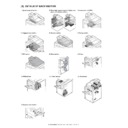
a. Paper feed tray units 1 and 2
1) Pull out the paper feed tray units 1 and 2.
2) Remove the fixing screws from the right and left rails.
3) Remove while holding the points shown in the diagram with two
hands.
a-1. Pickup roller
1) Pull out the paper feed tray units 1 and 2. (See “a. Paper feed tray
units 1 and 2”)
2) Unhook the claws to remove the paper guide.
3) Unhook the claw to lift up the first paper feed tray feed section, and
then remove the pickup roller.
a-2. Paper feed roller
1) Pull out the paper feed tray units 1 and 2. (See “a. Paper feed tray
units 1 and 2”)
2) Unhook the claws to remove the paper guide. (See “a-1. Pickup
roller”)
3) Unhook the claw to lift up the first paper feed tray feed section, and
then remove the paper feed roller.
a-3. Separation roller
1) Pull out the paper feed tray units 1 and 2. (See “a. Paper feed tray
units 1 and 2”)
2) Unhook the claws to remove the paper guide. (See “a-1. Pickup
roller”)
3) Remove the lower paper guide.
4) Unhook the claws to remove the reverse roller.
a-4. Torque limiter
1) Pull out the paper feed tray units 1 and 2. (See “a. Paper feed tray
units 1 and 2”)
2) Unhook the claws to remove the paper guide. (See “a-3. Separa-
tion roller”)
3) Remove the reverse roller unit.
AR-M550/M620 DETAILS OF EACH SECTION 6 - 17
4) Remove the torque limiter.
a-5. Lift wire (Rear)
1) Remove the paper feed tray units 1 and 2. (See “a. Paper feed
tray units 1 and 2” in “(Paper feed tray sections 1 and 2)”
2) Remove the E-ring, slide the winding pulley, and loosen the wire.
3) Release the pawl, and remove the wire.
4) Remove the plastic E-ring.
5) Remove the wire.
∗
Pass the nylon clamp.
∗
Attach so that the red wire is on the outside.
∗
Turn it clockwise to fit with the T-shape pin position and insert.
a-6. Lift wire (Front)
1) Remove the paper feed tray 1/2 unit. (See “(Paper feed tray sec-
tions 1 and 2)” in “a. Paper feed tray units 1 and 2”)
2) Push down the tray and remove the screw, and remove the paper
feed tray 1/2 front cabinet.
AR-M550/M620 DETAILS OF EACH SECTION 6 - 18
3) Remove the E-ring, slide the winding pulley, and loosen the wire.
4) Release the pawl, and remove the wire.
5) Remove the plastic E-ring.
6) Remove the wire.
∗
Pass the nylon clamp.
∗
Attach so that the red wire is on the outside.
∗
Turn it counterclockwise and fit with the T-shape pin position and
insert.
insert.
b-1. Paper remaining quantity sensor PWB
1) Remove the paper feed tray units 1 and 2. (See “a. Paper feed tray
units 1 and 2” in this section)
2) Disconnect the connector, and remove the paper remaining quan-
tity sensor PWB.
b-2. Paper remaining quantity detector
1) Remove the paper feed tray units 1 and 2. (See “a. Paper feed tray
units 1 and 2” in this section)
2) Disconnect the connector, and remove the paper feed tray lock
arm unit.
3) Disconnect the connector, and remove the paper remaining quan-
tity detector.
AR-M550/M620 DETAILS OF EACH SECTION 6 - 19
b-3. Paper feed trays 1 and 2 sensor
1) Remove the rear cabinet.
2) Disconnect the connector, and remove the paper feed trays 1 and
2 sensor.
b-4. Dry heater
1) Remove the rear cabinet. (See “b-3. Paper feed trays 1 and 2 sen-
sor” in this section)
2) Disconnect the connector from the dehumidifier heater relay PWB.
3) Remove the dry heater unit.
4) Remove the dry heater.
Click on the first or last page to see other AR-M550 (serv.man11) service manuals if exist.

