Sharp AR-M351U / AR-M451U (serv.man8) Service Manual ▷ View online
AR-M351U/M451U, AR-M355U/M455U EXTERNAL VIEWS AND INTERNAL STRUCTURES 5 - 5
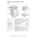
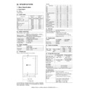
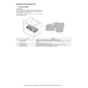
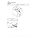
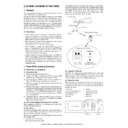
5. Cross sectional view
A. Scanner unit
B. Engine
No.
Name
No.
Name
1
CIS unit
10
Copy lamp base unit
2
Original resist roller
11
No. 1 mirror
3
Original resist front sensor (SPPD)
12
Copy lamp (Xenon)
4
Original set sensor (SPED)
13
Mirror base unit
5
Original take-up sensor
14
No. 3 mirror
6
Original length sensor 1 (SPLS1)
15
No. 2 mirror
7
Original length sensor 2 (SPLS2)
16
Original exit roller
8
CCD/lens unit
17
Original exit sensor
9
Original feed roller
No.
Name
No.
Name
1
OPC drum
14
Machine tray (Paper tray1) rotating plate
2
Main charger
15
Upper heat roller
3
Cleaning blade
16
Pressure roller
4
LSU
17
Heater lamp
5
Developing unit
18
Thermistor (RTH1 / RTH2)
6
Magnet roller
19
Thermostat
7
Toner hopper
20
Fusing back roller
8
Transfer roller
21
Reverse gate
9
Resist roller
22
Paper exit roller
10
Paper transport roller
23
Full detection lever
11
Machine tray (Paper tray1) paper feed roller
24
Printer control PWB
12
Machine tray (Paper tray1) separation roller
25
Power supply unit
13
Machine tray (Paper tray1) take-up roller
26
Cleaning roller
1
2
3 SPPD
4 SPED
5
6
7
8
9
10
11
12
13
14
15
16
17 SPOD
22
23
21
POD1 POD2 POD3
20
15
25
4
18
19
17
26
16
2
3
24
13
PED TUD
10
11
12
5
7
14
9
8
6
1
PPD1
AR-M351U/M451U, AR-M355U/M455U EXTERNAL VIEWS AND INTERNAL STRUCTURES 5 - 6
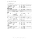
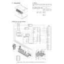
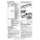
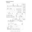
6. Switch, Sensor
A. Scanner unit
B. Engine
Code
Name
Active condition
1
SPPD
SPF original resist front sensor
2
SCOV
SPF paper feed cover sensor
3
SPED
SPF original set sensor
4
OCSW
OC open/close sensor
5
ORS-LED
Original size sensor PWB (Light emitting side)
6
SPLS1
SPF original length sensor 1
7
SPLS2
SPF original length sensor
8
SPFVR
SPF original width detection volume PWB
9
ORS-PD
Original size sensor PWB (Light receiving side)
10
SOCD
SPF open/close sensor
11
SPOD
SPF original exit sensor
12
MHPS
Mirror home position sensor
Code
Function/Operation
Active condition
1
DSW-F
Front door open/close detection
H= Door open
2
DSW-L
Left door open/close detection
H=Door open
3
POD1
Paper exit detection
L= Paper detection
4
POD2
Paper exit detection
L= Paper detection
5
POD3
Paper exit detection Full
L= Paper detection
6
PPD1
Paper transport detection
L= Paper detection
7
TCS
Toner concentration sensor
8
LUD
Paper feed cassette upper limit detection
H= Upper limit detection
9
PED
Paper feed cassette paper empty detection
L= Paper empty detection
10
MAIN SW
Power switch
7
1
2
3
4
5
6
8
9
10
11
12
1.DSW-F
2.DSW-L
3.POD1
4.POD2
5.POD3
6.PPD1
7.TCS
8.LUD
9.PED
10.MAIN SW
AR-M351U/M451U, AR-M355U/M455U EXTERNAL VIEWS AND INTERNAL STRUCTURES 5 - 7
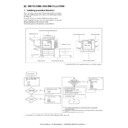
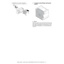
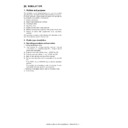
7. PWB
A. Scanner unit
B. Engine
No.
Name
Function/Operation
1
SPF control PWB
SPF control
2
Original size detection PWB (Light emitting side)
Original size detection when using the table glass
3
CCD PWB (in lens unit) (The lens unit cannot be disassembled.)
Image scan (Table glass/SPF surface)
4
SPF original width detection volume PWB
SPF original width detection
5
MFP operation PWB
Panel operation control
6
Scanner control PWB
Scanner unit control
7
LVDS PWB
LCD signal relay
8
Original size sensor (Light receiving side)
Original size detection when using the table glass
9
CIS unit (in CIS unit) (The CIS unit cannot be disassembled.)
Image scan (SPF back surface)
10
CIS interface PWB (in CIS unit) (The CIS unit cannot be disassembled.)
CIS signal AD conversion process
11
Scanner interface PWB
Scanner unit and connection of scanner control PWB
12
CIS control PWB
CIS unit control and image process
13
CL inverter PWB
Inverter for copy lamp
No.
Name
Function/Operation
1
PRT controller
Image process, image data communication control
2
PCU PWB
Overall control of the machine and options
3
Power supply unit
DC power supply
4
LD PWB (Inside LSU)
Laser ON control (Inside LSU: LSU cannot be disassembled.)
5
Mother PWB
Signal interface between PCU and the controller
6
Reactor PWB (200V only) / Filter PWB (Taiwan only)
Noise filter
7
BD PWB
Laser control (Inside LSU: LSU cannot be disassembled.)
8
High voltage resistor PWB
High voltage load adjustment
9
Cassette detection PWB
Paper cassette control
10
Drawer PWB
Fan control
11
High voltage PWB
High voltage power supply
12
Fuse PWB
Protection of the machine when an abnormal power is supplied.
13
Relay PWB
HDD back up
1
6
2
3
4
5
7
8
9
10
11
12
13
1
2
7
11
8
10
9
12
3
6
4
5
13
AR-M351U/M451U, AR-M355U/M455U EXTERNAL VIEWS AND INTERNAL STRUCTURES 5 - 8
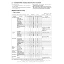
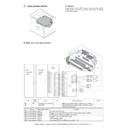
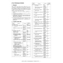
8. Motor, Clutch, Solenoid
A. Scanner unit
B. Engine
No.
Name
Function/Operation
1
SPFM
SPF motor
Original transport in SPF scan
2
SRRC
SPF original resist clutch
SPF original scan timing adjustment
3
SPFC
SPF original feed clutch
SPF original feed roller drive
4
SDSS
SPF original stopper solenoid
SPF original stopper gate drive
5
MIRM
Mirror motor
Mirror base copy lamp base drive
6
SPFS
SPF original feed solenoid
SPF original feed unit drive
7
STMPS
Stamp solenoid
Finish stamp drive (Option AR-SU1 required)
Code
Function/Operation
Type
1
DM
Drum motor
Brushless motor
2
MM
Main motor
Brushless motor
3
POM
Paper exit motor
Stepping motor
4
TM
Toner motor
Synchronous motor
5
LUM
Lift-up motor
Synchronous motor
6
VFM2
Heat exhaust fan motor
Fan motor
7
VFM1
Cooling fan motor
Fan motor
8
CFM1
Suction fan motor
Fan motor
10
CFM2
Ozone exhaust fan motor
Fan motor
11
CPFC
Paper cassette paper feed clutch
12
TRC
Paper transport clutch
13
PSPS
Separation solenoid
14
RRC
Resist roller clutch
15
HDDFAN
Cooling fan motor (for HDD)
Fan motor
16
CNTFAN
Cooling fan motor (for controller)
Fan motor
17
PM
Polygon motor
Polygon motor
1
2
3
4
5
6
7
1.DM
5.LUM
7.VFM1
8.CFM1
4.TM
14.RRC
12.TRC
2.MM
11.CPFC
6.VFM2
13.PSPS
16.CNTFAN
3.POM
10.CFM2
7.VFM1
15.HDDFAN
17.PM
Display

