Sharp AR-M351U / AR-M451U (serv.man16) Service Manual ▷ View online
AR-M351U/M451U, AR-M355U/M455U ADJUSTMENTS 8 - 16
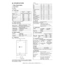
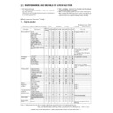
b. Adjust the fax mode print density (standard mode/
small-character mode/super fine mode/600dpi mode)
This adjustment is intended to the print mode for each Fax mode
individually. In manual mode, the print density setting for each
print density adjustment level (1 to 5) can be adjusted to a custom
density level.
individually. In manual mode, the print density setting for each
print density adjustment level (1 to 5) can be adjusted to a custom
density level.
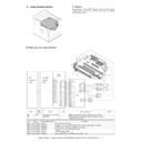
1) Set the test chart (UKOG-0162FCZZ) on the original table so
that it aligns with the front frame. Then put four or five pieces
of A3 (11" x 17") paper .
of A3 (11" x 17") paper .
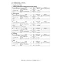
2) Go through the simulation modes that correspond to the Fax
modes for which to adjust the print density (i.e., the modes
specified in Simulations 46-13, -14, -15, -16, or -45).
specified in Simulations 46-13, -14, -15, -16, or -45).
Select 2, and
press [START] key.
press [START] key.
Press [START] key, or
press [CUSTOM SETTINGS] key.
press [CUSTOM SETTINGS] key.
00
SIMULATION 46-13
EXP.LEVEL SETUP FAX(NORMAL). SELECT 0-8, AND PRESS
START.
0.TRAY SELECT
1
1.PRINT START
2.EXP LEVEL
1
3.AUTO
50
4.1.0
50
5.2.0
50
6.3.0
50
7.4.0
50
8.5.0
50
50
1
1
Select 1,
and press
[START] key.
and press
[START] key.
Select 0, and press [START] key.
SIMULATION 46-13
EXP.LEVEL SETUP FAX(NORMAL),INPUT VALUE 0-99, AND
PRESS START.
4.1.0
SIMULATION 46-13
EXP.LEVEL SETUP FAX(NORMAL). NOW PRINTING.
SIMULATION 46-13
EXP.LEVEL SETUP FAX(NORMAL). SELECT 1-5, AND PRESS
START.
(FEED TRAY)
1.TRAY1 2.TRAY2 3.TRAY3 4.TRAY4
5.BPT
(ABOVE +20:DSPF MODE)
Select other than 0 - 2,
and press [START] key. Press [CUSTOM SETTINGS] key.
and press [START] key. Press [CUSTOM SETTINGS] key.
Press [START] key.
Press [CUSTOM SETTINGS] key,
or terminate copying.
or terminate copying.
Press [START] key, or
press [CUSTOM SETTINGS] key.
press [CUSTOM SETTINGS] key.
1
SIMULATION 46-13
EXP.LEVEL SETUP FAX(NORMAL). SELECT 3-8, AND PRESS START.
(EXP.LEVEL SELECT)
3.AUTO 4.1.0 5.2.0
6.3.0 7.4.0 8.5.0
Item
Set
range
Default
0 TRAY SELECT Paper feed tray selection
1 PRINT START Print start (Default)
2 EXP LEVEL
Exposure level selection
3 AUTO
Auto
0 - 99
50
4 1.0
Exposure level 1
5 2.0
Exposure level 2
6 3.0
Exposure level 3
7 4.0
Exposure level 4
8 5.0
Exposure level 5
Select 2, and
press [START] key.
press [START] key.
Press [START] key or
press [CUSTOM SETTINGS] key.
press [CUSTOM SETTINGS] key.
50
1
1
Select 1,
and press
[START] key.
and press
[START] key.
Select other than 0 - 2,
and press [START] key.
and press [START] key.
Press [CUSTOM SETTINGS] key.
Press [START] key.
Press [CUSTOM SETTINGS] key,
or terminate copying.
or terminate copying.
SIMULATION 46-14
EXP.LEVEL SETUP FAX(FINE).SELECT 0-14,AND PRESS START.
0.TRAY SELECT
1
1.PRINT START
2.EXP LEVEL
1
3.AUTO
50
4.1.0
50
5.2.0
50
6.3.0
50
7.4.0
50
8.5.0
50
9.AUTO(H)
50
10.1.0(H)
50
11.2.0(H)
50
12.3.0(H)
50
13.4.0(H)
50
14.5.0(H)
50
SIMULATION 46-14
EXP.LEVEL SETUP FAX(FINE),INPUT VALUE 0-99, AND PRESS
START.
4.1.0
Select 0, and press [START] key.
SIMULATION 46-14
EXP.LEVEL SETUP FAX(FINE). NOW PRINTING.
SIMULATION 46-14
EXP.LEVEL SETUP FAX(FINE). SELECT 1-5, AND PRESS START.
(FEED TRAY)
1.TRAY1 2.TRAY2 3.TRAY3 4.TRAY4
5.BPT
Press [START] key,
or press [CUSTOM SETTINGS] key.
or press [CUSTOM SETTINGS] key.
1
SIMULATION 46-14
EXP.LEVEL SETUP FAX(FINE). SELECT 3-14, AND PRESS START.
(EXP.LEVEL SELECT)
3.AUTO 4.1.0 5.2.0
6.3.0 7.4.0 8.5.0
9.AUTO(H) 10.1.0(H) 11.2.0(H)
12.3.0(H) 13.4.0(H) 14.5.0(H)
AR-M351U/M451U, AR-M355U/M455U ADJUSTMENTS 8 - 17
3) Using the numeric keypad, select the number that corre-
sponds to the adjustment item. Choose from numbers 3 to 8
(14).
(14).
• Auto mode
• Manual mode (print density adjustment level)
For manual mode, select the number that corresponds to the
print density level (1 to 5). (Choose from numbers (4 to 8) (10-
14)).
print density level (1 to 5). (Choose from numbers (4 to 8) (10-
14)).
4) Press the Start key
5) Press the Start key. (A copy is created.)
I.
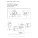
DSPF width detection adjustment
(1) When replacing DSPF unit
1) Use SIM53-7 to enter the value indicated on the side of the
right hinge of the DSPF unit.
(2) When replacing the original width detection
volume.
Execute SIM53-6 to perform the machine DSPF original tray size
adjustment.
adjustment.
1) Extend the guide to MAX. position, select 1, and press
START. When COMPLETE is displayed, press CUSTOM
SETTING to return to the initial screen.
SETTING to return to the initial screen.
2) Move the guide to A4R position, select 2, and press START.
When COMPLETE is displayed, press CUSTOM SETTING to
return to the initial screen.
return to the initial screen.
3) Move the guide to A5R position, select 3, and press START.
When COMPLETE is displayed, press CUSTOM SETTING to
return to the initial screen.
return to the initial screen.
4) Move the guide to MIN. position, select 4, and press START.
When COMPLETE is displayed, the adjustment is completed.
If ERROR is displayed in procedures 1) - 4), repeat the adjustment
again.
again.
Item
Set
range
Default
0 TRAY SELECT Paper feed tray selection
1 PRINT START Print start (Default)
1 PRINT START Print start (Default)
2 EXP LEVEL
Exposure level selection
3 AUTO
Auto
0 - 99
50
4 1.0
Exposure level 1
5 2.0
Exposure level 2
6 3.0
Exposure level 3
7 4.0
Exposure level 4
8 5.0
Exposure level 5
9 AUTO (H)
Auto (Half-tone)
10 1.0 (H)
Exposure level 1
(Half-tone)
(Half-tone)
11 2.0 (H)
Exposure level 2
(Half-tone)
(Half-tone)
12 3.0 (H)
Exposure level 3
(Half-tone)
(Half-tone)
13 4.0 (H)
Exposure level 4
(Half-tone)
(Half-tone)
14 5.0 (H)
Exposure level 5
(Half-tone)
(Half-tone)
Press [START] key.
Press [CUSTOM SETTINGS] key.
1
SIMULATION 53-7
SPF TRAY ADJUSTMENT(MANUAL). SELECT 1-4, AND PRESS
START.
1.MAX.POSITION:
66
2.POSITION 1 :
456
3.POSITION 2 :
713
4.MIN.POSITION:
791
66
SIMULATION 53-7
SPF TRAY ADJUSTMENT(MANUAL). INPUT VALUE 0-1023, AND
PRESS START.
1.MAX.POSITION
Select 4, and press [START] key.
Press [CUSTOM SETTINGS] key.
1
Select 2, and press [START] key.
Select 3, and press [START] key.
Press [CUSTOM SETTINGS] key.
Press [CUSTOM SETTINGS] key.
Press [CUSTOM SETTINGS] key.
SIMULATION 53-6
SPF TRAY ADJUSTMENT. SELECT 1-4, AND PRESS START.
1.MAX.POSITION
2.POSITION 1
3.POSITION 2
4.MIN.POSITION
SIMULATION 53-6
SPF TRAY ADJUSTMENT.
MAX.POSITION ... COMPLETE (or “ERROR”)
SIMULATION 53-6
SPF TRAY ADJUSTMENT.
POSITION 1 ... COMPLETE (or “ERROR”)
SIMULATION 53-6
SPF TRAY ADJUSTMENT.
POSITION 2 ... COMPLETE (or “ERROR”)
Select 1, and
press [START] key.
press [START] key.
SIMULATION 53-6
SPF TRAY ADJUSTMENT.
MIN.POSITION ... COMPLETE (or “ERROR”)

