Sharp AR-M351U / AR-M451U (serv.man16) Service Manual ▷ View online
AR-M351U/M451U, AR-M355U/M455U ADJUSTMENTS 8 - 2
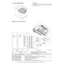
9) Move the adjustment plate in the arrow direction and adjust.
<Adjustment specification>
C. High voltage output adjustment
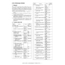
(1) Developing bias output check and setup
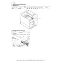
1) Remove the rear cabinet to allow checking of the high voltage
monitor output pin.
2) Execute the simulation of the target high voltage.
(See the table below.)
3) Select the mode to be set with 10-key, and press START key.
4) Enter the set value with 10-key and press START key. The set
value is outputted for 30 sec.
5) Apply a high voltage tester between the measurement pin and
the frame.
Note: Take care not to short the measuring pin and the frame.
6) The unit stops after 30 sec of output.
6) The unit stops after 30 sec of output.
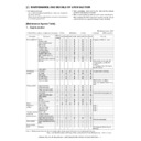
Specification
Marking position
Measure from
the P surface above.
the P surface above.
54.2mm
P
Default
Set range
Measurement
pin
High voltage
probe
impedance
Monitor output voltage
Set value
MC grid MAIN GRID
(SIM 8-2)
(SIM 8-2)
AUTO
AE mode
45PPM: -650V±5V
35PPM: -620V±5V
35PPM: -620V±5V
45PPM: 645
35PPM: 615
35PPM: 615
200~900
CN2-7
100M
Ω
CHARACTER Text mode
-650V±5V
645
200~900
MIX
Text/Photo mode
-650V±5V
645
200~900
PHOTO
Photo mode
-650V±5V
645
200~900
PRINTER
Printer mode
-650V±5V
645
200~900
FAX
Fax mode
-650V±5V
645
200~900
Transfer current
(THV+ (SIM 8-6)
(THV+ (SIM 8-6)
FRONT
Front
45PPM: 267
35PPM: 220
35PPM: 220
0~620
BACK
Back
45PPM: 310
35PPM: 267
35PPM: 267
0~620
Developing bias DV
BIAS (SIM 8-1)
BIAS (SIM 8-1)
AUTO
AE mode
45PPM: -500V±5V
35PPM: -470V±5V
35PPM: -470V±5V
485
0~745
CN2-1
100M
Ω
CHARACTER Text mode
-500V±5V
485
0~745
MIX
Text/Photo mode
-500V±5V
485
0~745
PHOTO
Photo mode
-500V±5V
485
0~745
PRINTER
Printer mode
-500V±5V
485
0~745
FAX
Fax mode
-500V±5V
485
0~745
PLUS
Positive bias
+150V±5V
150
0~255
Separation voltage SHV
(SIM 8-17)
(SIM 8-17)
FRONT
Front
45PPM: +0.22±0.1V
35PPM: +1.37V±0.1V
45PPM: 160
35PPM: 120
35PPM: 120
0~240
CN2-3
10M
Ω
BACK
Rear
45PPM : +0.22±0.1V
35PPM: +1.37V±0.1V
45PPM: 160
35PPM: 120
35PPM: 120
0~240
Transfer voltage THV
(SIM 8-17)
(SIM 8-17)
-800V±10V
780
0~1250
CN2-5
10G
Ω
AR-M351U/M451U, AR-M355U/M455U ADJUSTMENTS 8 - 3
2. Image check, adjustment
(1) Copy image check
1) Place a test chart (UKOG-0089CSZZ) on the reference posi-
tion of the OC, and make a copy.
2) Place a test chart (made as shown below) face-down on the
(D)SPF, set the document guide, and make a copy. (Single
→
Single)
3) Place a test chart (made as shown below) face-up on the
DSPF, set the document guide, and make a copy. (Duplex
→
Single)
4) Check each output copy.
(Image distortion/ each void/ lead edge position/ Off-center/
Magnification ratio/ Density/ Dirt, etc.)
Magnification ratio/ Density/ Dirt, etc.)
5) If there is no problem in copy images, the image check is com-
pleted.
(2) Division of adjustment positions
1) If there is any problem in checked images, perform self-print
and the adjustment positions (scanner side/ engine side) are
divided.
divided.
*:
If there is any problem in the copy image and no problem in
the self print, an adjustment on the scanner side is required.
the self print, an adjustment on the scanner side is required.
If there is any problem on the copy image and any problem in
the self print, an adjustment on the engine side is required.
the self print, an adjustment on the engine side is required.
(3) Adjustment procedures
Perform the adjustment procedures as described below.
A. Adjustments on the engine side
<1> LSU right angle adjustment
Items which must have been completed before this adjust-
ment.
ment.
• Nothing special
Items which must be executed after completion of this adjust-
ment.
ment.
• Print off-center adjustment
• Print lead edge adjustment
• Front/rear and left/right void amount setting
1) Execute SIM64-1.
2) The print pattern "71" is printed.
3) Check the output print.
4) Loosen two fixing screws of the LSU unit
(M4 screws which are fixing the LSU and the top plate).
5) Adjust the LSU fixing position with the adjustment memory as
the reference.
6) Tighten two fixing screws of the LSU unit.
7) Print again in the grid pattern and check the print.
8) Repeat procedures 4) to 7) until the specification is satisfied.
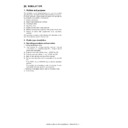
<Right angle check method>
<1> Make self-print of pattern 71.
<2> Draw a line perpendicular to the sub scan direction (paper
transport direction) with a square.
The point of intersection of the perpendicular line and the
horizontal line is regarded as the starting point.
The point of intersection of the perpendicular line and the
horizontal line is regarded as the starting point.
<3> Measure distance A (between the self-printed line and the
perpendicular line drawn with a square) at a position of
220mm from the starting point.
220mm from the starting point.
<4> Check that distance A satisfies the following specification.
Making of SFP test chart
a.
Use standard paper of A3.
b.
Mark to the full width of the paper so that each void/image
loss can be checked.
loss can be checked.
c.
At that time, mark so that the front /rear and the top/bottom
can be identified.
can be identified.
d.
Draw a center line in the paper transport direction to identify
the off center.
the off center.
1
LSU right angle adjustment
SIM64-1: Pattern “71”
2
Print off-center adjustment
SIM50-10
3
Each tray resist amount setting
SIM51-2
4
Print lead edge adjustment
SIM50-5
5
Front/rear and left/right void
amount setting
amount setting
SIM50-1
6
OC scan distortion adjustment
7
SPF height adjustment
8
SPF scan distortion
adjustment
adjustment
SIM51-2
9
Scan magnification ratio
SIM48-1
10
SPF/DSPF scan magnification
ratio
ratio
SIM48-1
11
OC scan lead edge adjustment
SIM50-1
12
SPF scan lead edge
adjustment
adjustment
SIM50-6
13
Original off-center adjustment
SIM50-12
Center line
Standard paper of A3
SIMULATION 64-1
SELF PRINT MODE. SELECT 0-7, AND PRESS START.
0. TRAY SELECT :
1
1. PRINT START
2. PRINT PATTERN:
87
3. DENSITY :
1
4. MULTI :
1
5. MODE :
1
6. LEVEL :
1
7. DUPLEX :
1
1
A
A
220mm
Print
lead edge
AR-M351U/M451U, AR-M355U/M455U ADJUSTMENTS 8 - 4
<Specification>
<2> Print off-center adjustment
Items which must have been completed before this adjust-
ment.
ment.
• LSU right angle adjustment (If there is no distortion in self print,
the adjustment is not required.)
Items which must be executed after completion of this adjust-
ment.
ment.
• Each tray resist amount setting
• Print lead edge adjustment
• Front/rear and left/right void amount setting
1) Execute SIM50-10.
2) Set the paper feed tray and the magnification ratio for the
adjustment.
3) After entering the adjustment values, press START key, and
printing is started.
4) Check the off-center (distance from the paper edge) of the
printed copy. Repeat procedure 2) until the specification is
satisfied.
satisfied.
• For the duplex mode (Single
→
Duplex), add 10 to the above set value.
• When the print line is shifted toward a from the paper center, decrease the value.
• When the print line is shifted toward b from the paper center, increase the value.
<3> Each tray resist amount setting
Items which must have been completed before this adjust-
ment.
ment.
• LSU right angle adjustment (If there is no distortion in self print,
the adjustment is not required.)
• Print off-center adjustment
Items which must be executed after completion of this adjust-
ment.
ment.
• Print lead edge adjustment
• Front/rear and left/right void amount setting
1) Execute SIM 51-2.
2) Enter the resist adjustment value with 10-key.
3) Press [START] key.
When [START] key is pressed, the adjustment value is set and
paper feed and copying are performed.
paper feed and copying are performed.
4) Adjust the resist quantity so that paper is transferred stably.
Measuring
point
Specification
Set value
Print
distortion
adjustment
distortion
adjustment
Self print
pattern 71
pattern 71
θ
= 90° ± 0.13°
θ
changes about 0.25
degrees for 1 scale of
adjustment. (A shifts
about 1mm.)
adjustment. (A shifts
about 1mm.)
a b
Print lead edge
2
SIMULATION 50-10
PRINT OFF-CENTER ADJUSTMENT. SELECT 0-8, AND PRESS
START.
0.TRAY SELECT
1
1.COPY START
2.MAGNIFICATION
100
(ADJUSTMENT DATA)
3.TRAY1
50
4.TRAY2
50
5.TRAY3
50
6.TRAY4
50
7.BPT
50
8.ADU
50
Adjustment position
Measurement
reference
Specification
Set value
Default
Range
Tray 1
Tray 1
Output pattern
center line
center line
0±1.5mm
50
0 - 99
Set value 1: 0.1mm shift
Tray 2
Tray 2
Tray 3
Tray 3/LCC left
Tray 4
Tray 4/LCC right
MFT
Manual feed
ADU
Duplex
a
b
Print lead edge
∗
This adjustment is executed when there is any lead edge vari-
ation or skew for each tray.
ation or skew for each tray.
1
SIMULATION 51-2
RESIST TIMING ADJUSTMENT. SELECT 0-8, AND PRESS START.
0.TRAY SELECT
1
1.PRINT START
2.TRAY1
60
3.TRAY2
50
4.DESK
50
5.BPT
55
6.ADU
50
7.SPF(HIGH)
60
8.SPF(LOW)
75
AR-M351U/M451U, AR-M355U/M455U ADJUSTMENTS 8 - 5
When the set value is increased, the warp amount of paper is
increased. When the adjustment value is decreased, the warp
amount of paper is decreased.
increased. When the adjustment value is decreased, the warp
amount of paper is decreased.
<4> Self print lead edge adjustment
Items which must have been completed before this adjust-
ment.
ment.
• LSU right angle adjustment (If there is no distortion in self print,
the adjustment is not required.)
• Print off-center adjustment
• Resist amount adjustment
Items which must be executed after completion of this adjust-
ment.
ment.
• Front/rear and left/right void amount setting
• OC scan lead edge adjustment
• SPF scan lead edge adjustment
1) Execute SIM 50-5.
2) Set the lead edge void adjustment value (DENA) as specified
2) Set the lead edge void adjustment value (DENA) as specified
below.
(Standard set value) Paper lead edge void: 3.5mm (DENA:
35)
35)
∗
Set the adjustment value of DENA to 35. (Enter 35 as the
adjustment value of DENA, and press [P] key.)
adjustment value of DENA, and press [P] key.)
3) Check the lead edge void area on the self print pattern
(SIM67-1).
(Enter 1 and press [START] key.)
4) If the adjustment result is not satisfactory, perform the follow-
ing procedures.
∗
If the lead edge void area is not 3.5mm:
Change the adjustment value of RRCB and perform the
adjustment. (Change the adjustment value of RRCB and
press [START] key.)
(Shift for the adjustment value change: 0.1mm/step)
Change the adjustment value of RRCB and perform the
adjustment. (Change the adjustment value of RRCB and
press [START] key.)
(Shift for the adjustment value change: 0.1mm/step)
<Specification>
<5> Front/rear and left/right void amount setting
Items which must have been completed before this adjust-
ment.
ment.
• LSU right angle adjustment (If there is no distortion in self print,
the adjustment is not required.)
• Print off-center adjustment
• Resist amount adjustment
• Print lead edge adjustment
Items which must be executed after completion of this adjust-
ment.
ment.
• OC scan lead edge adjustment
• SPF scan lead edge adjustment
1) Execute SIM 50-1.
(Lead edge image loss/void area adjustment)
(Lead edge image loss/void area adjustment)
1) Set the lead edge image loss adjustment value (LEAD EDGE)
and the paper lead edge void adjustment value (DENA) as fol-
lows.
lows.
(Standard set value)
Lead edge image loss: 1.5mm (LEDA: 15)
Lead edge image loss: 1.5mm (LEDA: 15)
Paper lead edge void: 3.5mm (DENA: 35)
∗
Set LEAD to 15. (Enter 15 as the adjustment value of LEAD,
and press [P] key.) (0.1mm/step)
and press [P] key.) (0.1mm/step)
∗
Set DENA to 35. (Enter 35 as the adjustment value of
DENA, and press [P] key.) (0.1mm/step)
DENA, and press [P] key.) (0.1mm/step)
2) Make a copy at the normal ratio (100%) and check the lead
edge void area and the image loss. (Enter 100 as the set value
of the copy magnification ratio (MAGNIFICATION), and press
[START] key.)
of the copy magnification ratio (MAGNIFICATION), and press
[START] key.)
3) If the adjustment result is not satisfactory, perform the follow-
ing procedures.
∗
If the lead edge void are is not 3.5mm:
Change the adjustment value of RRCB and perform the
adjustment. (Change the adjustment value of RRCB and
press [START] key.) (1msec/step)
Change the adjustment value of RRCB and perform the
adjustment. (Change the adjustment value of RRCB and
press [START] key.) (1msec/step)
∗
If the lead edge image loss is not 1.5mm:
Change the adjustment value of RRCA and perform the
adjustment. (Change the adjustment value of RRCA and
press [START] key.)
(Shift for the adjustment value change: 0.2mm/step)
Change the adjustment value of RRCA and perform the
adjustment. (Change the adjustment value of RRCA and
press [START] key.)
(Shift for the adjustment value change: 0.2mm/step)
(Rear edge void area adjustment)
Adjust so that the rear edge void area is 3.5mm. (Change the
adjustment value of TRAIL EDGE, and press [START] key.)
adjustment value of TRAIL EDGE, and press [START] key.)
(Front/rear frame direction image loss adjustment)
Set the adjustment value of SIDE to 20. (Enter 20 as the adjust-
ment value of SIDE, and press [P] key.)
ment value of SIDE, and press [P] key.)
When the adjustment value is changed, the image position is
shifted in the front/rear frame direction.
shifted in the front/rear frame direction.
(Front/rear frame direction void area adjustment)
Adjust so that the total of the front/rear direction void areas is
7.0mm. (Change the adjustment values of FRONT/REAR, and
press [START] key.)
7.0mm. (Change the adjustment values of FRONT/REAR, and
press [START] key.)
Front frame void area = 3.5mm
Rear frame void area = 3.5mm
If, as shown above, the front and the rear void areas are not even,
use SIM 50-5 to adjust the image off-center position.
use SIM 50-5 to adjust the image off-center position.
Item
Set
range
Default
AR-M351U/
M355U
AR-M451U/
M455U
2 TRAY1
Tray 1 resist
adjustment value
adjustment value
0 - 99
65
60
3 TRAY2
Tray 2 resist
adjustment value
adjustment value
55
50
4 DESK
Desk resist
adjustment value
adjustment value
55
50
5 BPT
Manual tray resist
adjustment value
adjustment value
60
55
6 ADU
ADU resist
adjustment value
adjustment value
55
50
Set position
Specification
Set value
Self print lead
edge
adjustment
SIM 50-5
edge
adjustment
SIM 50-5
Print start
position A of
the output
pattern 1
position A of
the output
pattern 1
A = 4.0mm or less
(Lead and tail
total: 8.0mm or
less)
(Lead and tail
total: 8.0mm or
less)
Shift of
0.175mm
(35ppm) /
0.225mm
(45ppm) for
set value 1.
0.175mm
(35ppm) /
0.225mm
(45ppm) for
set value 1.
2
SIMULATION 50-5
LEAD EDGE ADJUSTMENT. SELECT 0-20, AND PRESS START.
0.TRAY SELECT
LEAD EDGE ADJUSTMENT. SELECT 0-20, AND PRESS START.
0.TRAY SELECT
1
1.PRINT START
(ADJUSTMENT DATA)
LEAD EDGE: 2.RRCB
LEAD EDGE: 2.RRCB
50
3.SIDE2 ADJ.
50
RESIST: 4.T1
50
5.T2
50
6.DESK
50
7.BPT
50
8.ADU
50
OFF CENTER: 9.T1
50
10.T2
50
11.T3
50
12.T4
50
13.BPT
50
14.ADU
50
(VOID SETTING) 15.LEAD_EDGE(DENA)
50
16.TRAIL_EDGE(DENB)
30
17.FRONT/REAR
30
A
[Output pattern]

