Sharp AR-M351U / AR-M451U (serv.man13) Service Manual ▷ View online
AR-M351U/M451U, AR-M355U/M455U MAINTENANCE AND DETAILS OF EACH SECTION 7 - 38
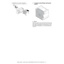
a-1. Paper dust remover unit
1) Open the front door.
2) Remove the paper dust cleaner unit.
b. Resist roller unit
1) Remove the paper dust cleaner unit.
2) Remove the screw, and remove the resist roller unit. Discon-
nect the connector.
b-1. Resist roller
1) Remove the paper dust cleaner unit.
2) Remove the resist roller unit.
3) Remove the parts, and remove the resist roller.
4) Remove the gear, the parallel pin, and the E-ring.
b-2. Paper transport roller
1) Remove the paper dust cleaner unit.
2) Remove the resist roller unit.
3) Remove the parts, and remove the paper transport roller.
b-3. Paper transport detection
b-4. High voltage resistor PWB
1) Remove the paper dust cleaner unit.
2) Remove the resist roller unit.
3) Remove the screw, and remove the paper dust cleaner guide.
AR-M351U/M451U, AR-M355U/M455U MAINTENANCE AND DETAILS OF EACH SECTION 7 - 39
4) Remove the screw and the connector, and remove the paper
transport detector.
5) Remove the screw and the earth wire, and remove the high
voltage resistor PWB.
c. Left door unit
1) Remove the screw, and remove the left door unit.
c-1. Suction fan motor
c-2. High voltage resistor PWB
1) Remove the left door unit.
2) Remove the screw, and remove the transfer lock pawl.
3) Remove the screw, and remove the left door transport paper
guide.
3) Remove the connector, the screw, and the washer, and
remove the suction fan motor.
4) Remove the screw, and remove the high voltage resistor
PWB.
∗
When installing the fan, check the left door indication arrow and
note the fan direction.
note the fan direction.
c-3. Drawer PWB
1) Remove the left door unit.
2) Remove the left door transport paper guide.
3) Remove the screw, and the reverse gate unit and remove the
angle.
4) Remove the screw, and remove the angle.
5) Remove the connector, the screw, and remove the drawer
PWB.
AR-M351U/M451U, AR-M355U/M455U MAINTENANCE AND DETAILS OF EACH SECTION 7 - 40
d. Paper exit reverse unit
1) Pull out the left door.
2) Remove the screw, and remove the rear cabinet.
3) Remove the screw, and remove the paper exit upper cabinet.
4) Remove the screw, and remove the left rear cabinet.
5) Remove the screw, and remove the front left upper cabinet.
6) Remove the screw, and remove the paper exit tray cabinet.
7) Remove the screw, and remove the front right upper cabinet.
8) Remove the front door.
9) Remove the E-ring and the parts.
10) Remove the screw and the connector, and remove the paper
exit reverse unit.
d-1. Paper exit detection 1
1) Remove the paper exit reverse unit.
2) Remove the actuator. Remove the connector, and remove the
paper exit detection 1.
AR-M351U/M451U, AR-M355U/M455U MAINTENANCE AND DETAILS OF EACH SECTION 7 - 41
d-2. Paper exit motor
1) Remove the paper exit reverse unit.
2) Remove the connector and the screw, and remove the paper
exit motor.
d-3. Left door open/close detection
1) Remove the paper exit reverse unit.
2) Remove the connector and the screw, and remove the left
door open/close detection.
d-4. Exhaust heat fan motor
d-5. Paper exit detection 2
d-6. Paper exit full detection
1) Remove the paper exit reverse unit.
2) Remove the screw, and remove the exhaust duct.
3) Remove the screw, and remove the paper exit upper paper
guide reinforcement plate.
4) Remove the connector, the exhaust heat fan, the paper exit
detection 2, the paper exit full detection.
∗
When installing the fan, check the indication arrow and note the
fan direction.
fan direction.
d-7. After-fusing roller
1) Remove the paper exit reverse unit.
2) Remove the E-ring and the parts.
3) Remove the connector and the screw, and remove the paper
exit drive frame.
4) Remove the bearing, the E-ring, and the parts.
5) Remove the E-ring, and remove the fusing rear roller. Remove
the bearing.
Click on the first or last page to see other AR-M351U / AR-M451U (serv.man13) service manuals if exist.

