|
|
AR-M351U AR-M451U (serv.man3)
Front Back Covers
Service Manual
|
9
|
2.62 MB
|
|
|
AR-M351U AR-M451U (serv.man4)
General
Service Manual
|
1
|
45 KB
|
|
|
AR-M351U AR-M451U (serv.man5)
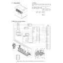
Configuration
Service Manual
|
4
|
153.04 KB
|
|
|
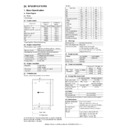
AR-M351U AR-M451U (serv.man6)
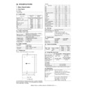
Specifications
Service Manual
|
9
|
113.49 KB
|
|
|
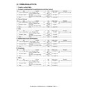
AR-M351U AR-M451U (serv.man7)
Consumable Parts
Service Manual
|
4
|
87.61 KB
|
|
|
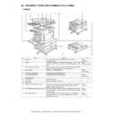
AR-M351U AR-M451U (serv.man8)
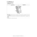
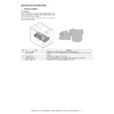
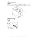
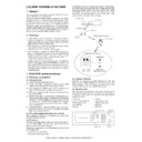
External Views Internal Structures.
Service Manual
|
8
|
476.72 KB
|
|
|
AR-M351U AR-M451U (serv.man9)
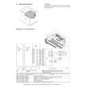
Unpacking and Installation
Service Manual
|
14
|
1.31 MB
|
|
|
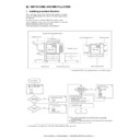
AR-M351U AR-M451U (serv.man10)
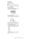
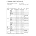
Maintenance details of following sections, (Maintenance System Table)
Service Manual
|
3
|
60.82 KB
|
|
|
AR-M351U AR-M451U (serv.man11)
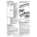
Maintenance details of following sections, 1-Process
Service Manual
|
17
|
1.78 MB
|
|
|
AR-M351U AR-M451U (serv.man12)
Maintenance details of following sections, 2-Fuser, 3-Paper Feed
Service Manual
|
12
|
1.29 MB
|
|
|
AR-M351U AR-M451U (serv.man14)
Maintenance details of following sections, 5-Laser Scanner, 6-Scanner, 7-DSPF, 8-Operation Panel
Service Manual
|
23
|
2.37 MB
|
|
|
AR-M351U AR-M451U (serv.man15)
Maintenance details of following sections, 9-Filter, 10-Drive Section, 11-Power section, 12-PWB, 13-Fan Motor.
Service Manual
|
10
|
2.64 MB
|
|
|
AR-M351U AR-M451U (serv.man16)
Adjustments
Service Manual
|
17
|
1.78 MB
|
|
|
AR-M351U AR-M451U (serv.man17)
Simulations
Service Manual
|
88
|
887.33 KB
|
|
|
AR-M351U AR-M451U (serv.man18)
Machine Operation
Service Manual
|
3
|
137.33 KB
|
|
|
AR-M351U AR-M451U (serv.man19)
Trouble Codes
Service Manual
|
16
|
185.89 KB
|
|
|
AR-M351U AR-M451U (serv.man20)
Rom Version Up Method
Service Manual
|
5
|
261.26 KB
|
|
|
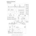
AR-M351U AR-M451U (serv.man21)
Electrical
Service Manual
|
23
|
253.27 KB
|

|
AR-M351U AR-M451U (serv.man22)
Complete Service Manual
Service Manual
|
|
14.49 MB
|

|
AR-M351U AR-M451U
ARM351 451 Mac PPD for MacOS 10.5. Mac OS
Drivers
|
|
1.63 MB
|

|
AR-M351U AR-M451U (serv.man59)
ARM236 256 276 316 351 451 550 620 700 PS Driver for Windows Vista 64Bit. Version 801a WHQL signed. Windows Vista
Drivers
|
|
10.76 MB
|

|
AR-M351U AR-M451U (serv.man60)
Windows Vista PCL6 64 Bit Driver. Windows Vista
Drivers
|
|
5.86 MB
|

|
AR-M351U AR-M451U (serv.man61)
Windows Vista PCL6 Driver. This diver can be used in conjunction with 64 Bit printer driver. Windows Vista
Drivers
|
|
5.17 MB
|

|
AR-M351U AR-M451U (serv.man62)
Windows Vista PCL6 Driver. Windows Vista
Drivers
|
|
2.94 MB
|

|
AR-M351U AR-M451U (serv.man63)
Windows Vista PCL5e Driver. Windows Vista
Drivers
|
|
2.29 MB
|

|
AR-M351U AR-M451U (serv.man64)
Windows 2000 PCL6 64 Bit Driver. Windows 2000
Drivers
|
|
5.86 MB
|

|
AR-M351U AR-M451U (serv.man65)
Windows 2000 PCL6 Driver. This diver can be used in conjunction with 64 Bit printer driver. Windows 2000
Drivers
|
|
5.17 MB
|

|
AR-M351U AR-M451U (serv.man66)
CD Ver 2.03 - Production Run Date 09 11 2005. This Driver is WHQL compliant. Windows 2000
Drivers
|
|
2.87 MB
|

|
AR-M351U AR-M451U (serv.man67)
CD Ver 2.03 - Production Run Date 09 11 2005. This Driver is WHQL compliant. Windows 2000
Drivers
|
|
2.21 MB
|

|
AR-M351U AR-M451U (serv.man68)
Win2K PCL6 Driver (Ver 2.00d.001) From Production Run Date 31 10 2005. Windows 2000
Drivers
|
|
2.86 MB
|

|
AR-M351U AR-M451U (serv.man69)
Win2K PCL5e Driver (Ver 2.00d.001) From Production Run Date 31 10 2005. Windows 2000
Drivers
|
|
2.2 MB
|

|
AR-M351U AR-M451U (serv.man70)
AR-M351N-M351U-M451N-M451U PPD Driver for Win2K, v2.01(v2.00a.004) Supporting Win2K 2003 Server WHQL (Including 'Add Printer' Wizard support). Windows 2000
Drivers
|
|
17.1 KB
|

|
AR-M351U AR-M451U (serv.man71)
AR-M351N-M351U-M451N-M451U PCL6 Driver for Win2K, v2.01(v2.00a.004) Supporting Win2K 2003 Server WHQL (Including 'Add Printer' Wizard support). Windows 2000
Drivers
|
|
2.87 MB
|

|
AR-M351U AR-M451U (serv.man72)
AR-M351N-M351U-M451N-M451U PCL5e Driver for Win2K, v2.01(v2.00a.004) Supporting Win2K 2003 Server WHQL (Including 'Add Printer' Wizard support). Windows 2000
Drivers
|
|
2.21 MB
|

|
AR-M351U AR-M451U (serv.man73)
ARM236 256 276 316 351 451 550 620 700 PS Driver for Windows XP 64Bit. Version 801a WHQL signed. Windows XP
Drivers
|
|
10.76 MB
|

|
AR-M351U AR-M451U (serv.man74)
Windows XP PCL6 64 Bit Driver. Windows XP
Drivers
|
|
5.86 MB
|

|
AR-M351U AR-M451U (serv.man75)
Windows XP PCL6 Driver. This diver can be used in conjunction with 64 Bit printer driver. Windows XP
Drivers
|
|
5.17 MB
|

|
AR-M351U AR-M451U (serv.man76)
Production Run Date 27 12 2005. Windows XP
Drivers
|
|
31.85 KB
|

|
AR-M351U AR-M451U (serv.man77)
CD Ver 2.03 - Production Run Date 09 11 2005. This Driver is WHQL compliant. Windows XP
Drivers
|
|
2.87 MB
|

|
AR-M351U AR-M451U (serv.man78)
CD Ver 2.03 - Production Run Date 09 11 2005. This Driver is WHQL compliant. Windows XP
Drivers
|
|
2.21 MB
|

|
AR-M351U AR-M451U (serv.man79)
WinXP PCL6 Driver (Ver 2.00d.001) From Production Run Date 31 10 2005. Windows XP
Drivers
|
|
2.86 MB
|

|
AR-M351U AR-M451U (serv.man80)
WinXP PCL5e Driver (Ver 2.00d.001) From Production Run Date 31 10 2005. Windows XP
Drivers
|
|
2.2 MB
|

|
AR-M351U AR-M451U (serv.man81)
AR-M351N-M351U-M451N-M451U PPD Driver for WinXP, v2.01(v2.00a.004) Supporting Win2K 2003 Server WHQL (Including 'Add Printer' Wizard support). Windows XP
Drivers
|
|
17.1 KB
|

|
AR-M351U AR-M451U (serv.man82)
AR-M351N-M351U-M451N-M451U PCL6 Driver for WinXP, v2.01(v2.00a.004) Supporting Win2K 2003 Server WHQL (Including 'Add Printer' Wizard support). Windows XP
Drivers
|
|
2.87 MB
|

|
AR-M351U AR-M451U (serv.man83)
AR-M351N-M351U-M451N-M451U PCL5e Driver for WinXP, v2.01(v2.00a.004) Supporting Win2K 2003 Server WHQL (Including 'Add Printer' Wizard support). Windows XP
Drivers
|
|
2.21 MB
|

|
AR-M351U AR-M451U (serv.man84)
CD Ver 2.03 - Production Run Date 09 11 2005. This Driver is WHQL compliant. Windows NT4
Drivers
|
|
2.79 MB
|

|
AR-M351U AR-M451U (serv.man85)
CD Ver 2.03 - Production Run Date 09 11 2005. This Driver is WHQL compliant. Windows NT4
Drivers
|
|
2.21 MB
|

|
AR-M351U AR-M451U (serv.man86)
WinNT4.0 PCL6 Driver (Ver 2.00d.001) From Production Run Date 31 10 2005. Windows NT4
Drivers
|
|
2.79 MB
|

|
AR-M351U AR-M451U (serv.man87)
WinNT4.0 PCL5e Driver (Ver 2.00d.001) From Production Run Date 31 10 2005. Windows NT4
Drivers
|
|
2.21 MB
|

|
AR-M351U AR-M451U (serv.man88)
AR-M351N-M351U-M451N-M451U PPD Driver for WinNT4.0, v2.01(v2.00a.004) Supporting Win2K 2003 Server. Windows NT4
Drivers
|
|
89.49 KB
|

|
AR-M351U AR-M451U (serv.man89)
AR-M351N-M351U-M451N-M451U PCL6 Driver for WinNT4.0, v2.01(v2.00a.004) Supporting Win2K 2003 Server. Windows NT4
Drivers
|
|
2.79 MB
|

|
AR-M351U AR-M451U (serv.man90)
AR-M351N-M351U-M451N-M451U PCL5e Driver for WinNT4.0, v2.01(v2.00a.004) Supporting Win2K 2003 Server. Windows NT4
Drivers
|
|
2.21 MB
|

|
AR-M351U AR-M451U (serv.man91)
CD Ver 2.03 - Production Run Date 09 11 2005. This Driver is WHQL compliant. Windows ME
Drivers
|
|
2.89 MB
|

|
AR-M351U AR-M451U (serv.man92)
CD Ver 2.03 - Production Run Date 09 11 2005. This Driver is WHQL compliant. Windows ME
Drivers
|
|
2.59 MB
|

|
AR-M351U AR-M451U (serv.man93)
WinMe PCL6 Driver (Ver 2.00d.001) From Production Run Date 31 10 2005. Windows ME
Drivers
|
|
2.89 MB
|

|
AR-M351U AR-M451U (serv.man94)
WinMe PCL5e Driver (Ver 2.00d.001) From Production Run Date 31 10 2005. Windows ME
Drivers
|
|
2.59 MB
|

|
AR-M351U AR-M451U (serv.man95)
AR-M351N-M351U-M451N-M451U PPD Driver for WinMe, v2.01(v2.00a.004) Supporting Win2K 2003 Server. Windows ME
Drivers
|
|
171.99 KB
|

|
AR-M351U AR-M451U (serv.man96)
AR-M351N-M351U-M451N-M451U PCL6 Driver for WinMe, v2.01(v2.00a.004) Supporting Win2K 2003 Server. Windows ME
Drivers
|
|
2.89 MB
|

|
AR-M351U AR-M451U (serv.man97)
AR-M351N-M351U-M451N-M451U PCL5e Driver for WinMe, v2.01(v2.00a.004) Supporting Win2K 2003 Server. Windows ME
Drivers
|
|
2.59 MB
|

|
AR-M351U AR-M451U (serv.man98)
CD Ver 2.03 - Production Run Date 09 11 2005. This Driver is WHQL compliant. Windows 98
Drivers
|
|
2.92 MB
|

|
AR-M351U AR-M451U (serv.man99)
CD Ver 2.03 - Production Run Date 09 11 2005. This Driver is WHQL compliant. Windows 98
Drivers
|
|
2.62 MB
|

|
AR-M351U AR-M451U (serv.man100)
Win9x PCL6 Driver (Ver 2.00d.001) From Production Run Date 31 10 2005. Windows 98
Drivers
|
|
2.92 MB
|

|
AR-M351U AR-M451U (serv.man101)
Win9x PCL5e Driver (Ver 2.00d.001) From Production Run Date 31 10 2005. Windows 98
Drivers
|
|
2.62 MB
|

|
AR-M351U AR-M451U (serv.man102)
AR-M351N-M351U-M451N-M451U PPD Driver for Win9X, v2.01(v2.00a.004) Supporting Win2K 2003 Server. Windows 98
Drivers
|
|
171.99 KB
|

|
AR-M351U AR-M451U (serv.man103)
AR-M351N-M351U-M451N-M451U PCL6 Driver for Win9X, v2.01(v2.00a.004) Supporting Win2K 2003 Server. Windows 98
Drivers
|
|
2.92 MB
|

|
AR-M351U AR-M451U (serv.man104)
AR-M351N-M351U-M451N-M451U PCL5e Driver for Win9X, v2.01(v2.00a.004) Supporting Win2K 2003 Server. Windows 98
Drivers
|
|
2.62 MB
|
|
|
AR-M351U AR-M451U (serv.man23)
April 10
Service Manual / Parts Guide
|
93
|
4.54 MB
|
|
|
AR-M351U AR-M451U (serv.man2)
General Specifications taken from Service Manual.
Service Manual / Specification
|
9
|
113.49 KB
|
|
|
AR-M351U AR-M451U (serv.man41)
Parts change for productivity improvement.
Service Manual / Technical Bulletin
|
3
|
184.15 KB
|
|
|
AR-M351U AR-M451U (serv.man42)
PARTS GUIDE CORRECTION
Service Manual / Technical Bulletin
|
1
|
15.49 KB
|
|
|
AR-M351U AR-M451U (serv.man43)
ARE-902 SMUDGY IMAGE RECEPTION RESULTING FROM INCOMPLETE MG ROLLER ROTATION
Service Manual / Technical Bulletin
|
2
|
69.87 KB
|
|
|
AR-M351U AR-M451U (serv.man44)
ENHANCEMENT OF STRENGTH OF DSPF (SPF) ADJUST PLATES F R.
Service Manual / Technical Bulletin
|
2
|
409.12 KB
|
|
|
AR-M351U AR-M451U (serv.man45)
PREVENTING THE DRUM FROM BEING SCRATCHED DUE TO INSERTION REMOVAL OF THE PROCESS UNIT.
Service Manual / Technical Bulletin
|
2
|
544.3 KB
|
|
|
AR-M351U AR-M451U (serv.man46)
012 Rom Upgrade (8)
Service Manual / Technical Bulletin
|
5
|
39.78 KB
|
|
|
AR-M351U AR-M451U (serv.man47)
010-Power on off operation caused By pcu pwb malfunction.
Service Manual / Technical Bulletin
|
2
|
202.93 KB
|
|
|
AR-M351U AR-M451U (serv.man48)
Firmware updating procedure to resolve overtoning.
Service Manual / Technical Bulletin
|
1
|
17.36 KB
|
|
|
AR-M351U AR-M451U (serv.man49)
AREF3 DSPF Multifeed and misfeeding issues.
Service Manual / Technical Bulletin
|
5
|
896.4 KB
|
|
|
AR-M351U AR-M451U (serv.man50)
Rom Upgrade..5
Service Manual / Technical Bulletin
|
2
|
64.52 KB
|
|
|
AR-M351U AR-M451U (serv.man51)
006-Change to new type flash ROM (ELEM)
Service Manual / Technical Bulletin
|
2
|
140.55 KB
|
|
|
AR-M351U AR-M451U (serv.man52)
005-Making LCD, FFC and LVDS INV board service parts available as a kit.
Service Manual / Technical Bulletin
|
2
|
58.16 KB
|
|
|
AR-M351U AR-M451U (serv.man53)
Change in I F connectors for coin vendors.
Service Manual / Technical Bulletin
|
1
|
25.42 KB
|
|
|
AR-M351U AR-M451U (serv.man54)
ROM Upgrade..4
Service Manual / Technical Bulletin
|
2
|
16.99 KB
|
|
|
AR-M351U AR-M451U (serv.man55)
Additions to details described in simulation 62-10.
Service Manual / Technical Bulletin
|
1
|
36.83 KB
|
|
|
AR-M351U AR-M451U (serv.man56)
ROM Upgrade 3
Service Manual / Technical Bulletin
|
2
|
11.49 KB
|

|
AR-M351U AR-M451U (serv.man25)
Twain Driver for ARM351 451
Driver / Update
|
|
4.59 MB
|

|
AR-M351U AR-M451U (serv.man26)
Firmware Version VN1.16 NON ELEM
Driver / Update
|
|
13.08 MB
|

|
AR-M351U AR-M451U (serv.man27)
Firmware Version VN1.16 ELEM
Driver / Update
|
|
13.14 MB
|

|
AR-M351U AR-M451U (serv.man28)
PCU firmware to prevent overtoning.
Driver / Update
|
|
179.68 KB
|

|
AR-M351U AR-M451U (serv.man29)
New firmware for AR-M351U 451U.Fitted with AR-NC7 which is P version. Main n1h15,Boot n1.5d,scanner 01.03.01,PCU 01.03.01. For tray switching issues.
Driver / Update
|
|
13.19 MB
|

|
AR-M351U AR-M451U (serv.man30)
New firmware for AR-M351U 451U.Fitted with AR-NC8 which is N version. Main n1h15,Boot n1.5d,scanner 01.03.01,PCU 01.03.01. For tray switching issues.
Driver / Update
|
|
13.24 MB
|

|
AR-M351U AR-M451U (serv.man31)
New firmware for AR-M351U 451U.Main n1h15,Boot n1.5d,scanner 01.03.01,PCU 01.03.01. For tray switching issues.
Driver / Update
|
|
13.19 MB
|

|
AR-M351U AR-M451U (serv.man32)
Main up to Vn1.15, Boot up to VN1.5D. Change details enclosed.
Driver / Update
|
|
13.3 MB
|

|
AR-M351U AR-M451U (serv.man33)
Main up to Vn1.15, Boot up to VN1.5D. Change details enclosed.
Driver / Update
|
|
13.29 MB
|

|
AR-M351U AR-M451U (serv.man34)
Main up to Vp1.15, Boot up to VP1.5D. Change details enclosed.
Driver / Update
|
|
13.24 MB
|

|
AR-M351U AR-M451U (serv.man35)
Main up to Vp1.15, Boot up to VP1.5D. Change details enclosed.
Driver / Update
|
|
13.25 MB
|

|
AR-M351U AR-M451U (serv.man36)
Main up to Vu1.15, Boot up to Vu1.5D. Change details enclosed.
Driver / Update
|
|
13.25 MB
|

|
AR-M351U AR-M451U (serv.man37)
Main up to Vu1.15, Boot up to Vu1.5D. Change details enclosed.
Driver / Update
|
|
13.24 MB
|

|
AR-M351U AR-M451U (serv.man38)
Common PC Fax Driver (v2.3.0.110) for Andromeda, Pegasus E, Tiger, Jupiter and Dragon Products.
Driver / Update
|
|
16.61 MB
|

|
AR-M351U AR-M451U (serv.man39)
Firmware Revision Control No C01 Main Vu1.14, Boot VU1.5A, PCU V01.03, SCN V01.03. Firmware upgrade Utility and change history enclosed.
Driver / Update
|
|
13.22 MB
|

|
AR-M351U AR-M451U (serv.man40)
Firmware Upgrade Utility.
Driver / Update
|
|
119 KB
|

|
AR-M351U AR-M451U (serv.man24)
A complete list of PCL, HPGL, PJL and PS commands, sometimes called escape codes for Jupiter.
FAQ
|
|
98.26 KB
|
|
|
AR-M351U AR-M451U (serv.man57)
MSDS (F31331) for Black Developer, (AR-455DV).
Regulatory Data
|
4
|
32.67 KB
|
|
|
AR-M351U AR-M451U (serv.man58)
MSDS (FO1331) for Black Toner, (AR-455T).
Regulatory Data
|
4
|
35.56 KB
|

