Sharp AR-M351U / AR-M451U (serv.man13) Service Manual ▷ View online
AR-M351U/M451U, AR-M355U/M455U MAINTENANCE AND DETAILS OF EACH SECTION 7 - 33
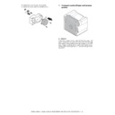
3) Remove the E-ring, the gear, and the spring.
4) Remove the screw, and remove the lift-up motor.
4. Transport section/Paper exit reverse
section
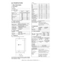
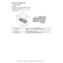
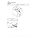
A. General
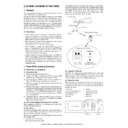
In this paper transport section, paper fed from each paper feed
port is transported to the resist roller section, where the lead edge
of the paper is aligned with the lead edge of images on the OPC
drum. Images are transferred onto paper in the transfer section,
and the paper is discharged face-up or face-down through the fus-
ing section.
port is transported to the resist roller section, where the lead edge
of the paper is aligned with the lead edge of images on the OPC
drum. Images are transferred onto paper in the transfer section,
and the paper is discharged face-up or face-down through the fus-
ing section.
AR-M351U/M451U, AR-M355U/M455U MAINTENANCE AND DETAILS OF EACH SECTION 7 - 34
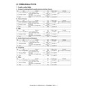
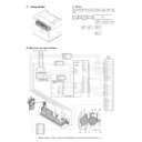
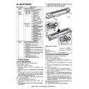
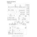
B. Major parts and signal functions
DSW-F
MM-T
GND2
+5V1
GND2
MM\
9604S-08C
1
2
3
4
5
6
7
8
CN9
DSW-F
GND2
SMR-06V+SMP-06V-NC
/POMB
4
/POMXB
/POMA
/POMXA
+24V1
3
1
1
6
5
2
3
2
5
4
+24V1
6
BR
BR
BR
BR
RD
RD
HVR
PWB
GY
HVR
PWB
GY
SFPS-41T-187
RD
RD
PHNR-03-H+BU03P-TR-P-H
+24V1
3
1
3
VFM2\
2
GND2
1
2
RD
GY
BR
PHNR-03-H+BU03P-TR-P-H
BR
PHR-3
CFM1\
BR
DRAWER
PWB
+24V1
1
2
3
RD
3
3
+24V1
1
4
GY
1
2
2
TSR-04V-K
CFM1\
+24V1
3
RD
CFM1\
GND2
GND2
GY
2
GND2
1
GND2
BR
GY
GY
RD
+24V1
RRC\
1
1
2
2
PHNR-02-H+BU02P-TR-P-H
RD
BR
+24V1
TRC1\
1
1
2
2
(NC)
3
3
PHNR-03-H+BU03P-TR-P-H
RD
BR
GND2
+5V2
GND2
GND2
PED
+5V2
+5V2
LUD
PPD1
1
2
3
4
5
6
7
8
9
1
2
3
4
5
6
7
8
9
PHNR-09-H+BU09P-TR-P-H
BL
GY
BR
2
+5V2
PPD1
1
GND2
2
PPD1
1
3
3
1
GND2
+5V2
3
179228-3(AMP)
2
PHNR-03-H+BU03P-TR-P-H
GY
BL
BR
BL
BR
GY
POD1
GND2
1
2
3
179228-3
+5V2
3
2
179228-3
POD2
1
GND2
+5V2
3
POD3
179228-3
GND2
2
1
POD1
+5V2
GND2
2
1
2
SMP-03V-BC+SMR-03V-B
3
1
3
BL
GY
BR
GY
GY
GY
GY
BL
BL
BL
BL
BR
BR
BR
BR
+5V2
DSW-L
MM-T
GND2
+5V2
GND1
MM\
8
7
6
5
4
3
2
1
DSW-L
GND1
8FE-ST-VK-N
MM
POM
POD3
POD2
POD1
DSW-L
RRC
VFM2
PPD1
TRC
CFM1
POD3
POD1
POD2
/POMA
/POMXA
GND2
/POMXB
+5V2
/POMB
2
3
4
5
6
7
8
9
10
11
12
13
14
CN4
CFM2\
1
+24V1
+24V1
DSW-L
15
16
17
18
+5V2
GND2
+5V2
19
20
21
22
GND2
+24V1
+24V1
TRC\
LUMA
PED
CPFC\
PPD1
CSS
LUMB
LUD
RRC\
GND2
+5V2
GND2
+24V1
18
1
2
3
4
5
6
7
8
9
10
11
12
13
14
15
16
17
GND
19
20
GND2
+5V2
+5V2
GND2
21
22
23
24
+24V1
CFM1\
GND2
GND2
+24V1
GND2
+24V1
23
24
25
26
27
28
29
30
32
31
+24V1
VFM2\
+24V1
GND2
(NC)
GND2
(NC)
DSW-L
(NC)
(NC)
DSW-F
RD
GY
BL
RD
BR
BR
BR
BR
RD
GY
GY
BL
RD
RD
GY
GY
GY
BL
BL
RD
RD
RD
GY
BR
BR
BR
BR
BR
BR
BR
CFM2\
B24B-PHDSS-B
B32B-PHDSS-B
CN13
PCU PWB
5
2
4
1
5
4
3
2
1
Code
Signal
name
Name
Function/Operation
Type
Note
POD1
POD1
Paper exit detector 1
Paper exit detection from fusing
Transmission
type
type
Paper transport system sensor
POD2
POD2
Paper exit detector 2
Paper pass detection from paper exit
Transmission
type
type
Paper transport system sensor
POD3
POD3
Paper exit detector 3
Paper exit detection to upper section
paper exit tray (Full detection)
paper exit tray (Full detection)
Transmission
type
type
Paper transport system sensor
POM
POM
Paper exit motor
Drives the paper exit roller.
Stepping
motor
motor
Selection of Normal speed/
High speed/ Reverse rotation
High speed/ Reverse rotation
VFM2
VFM2
Fusing cooling fan motor
Discharges heat generated in the
fusing section.
fusing section.
DC brushless
motor
motor
PWM control
CFM1
CFM1
Fusing cooling fan motor
Discharges heat generated in the
fusing section to cool it.
fusing section to cool it.
DC brushless
motor
motor
PWM control
AR-M351U/M451U, AR-M355U/M455U MAINTENANCE AND DETAILS OF EACH SECTION 7 - 35
C. Operational descriptions
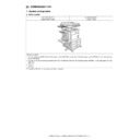
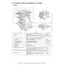
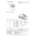
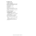
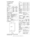
[Paper transport path and paper exit]
Paper transport path with an option installed
1.
2.
Code
Signal
name
Name
Function/Operation
Type
Note
RRC
RRC
Resist roller clutch
Resist roller ON/OFF control
Electromagnetic
clutch
clutch
TRC
TRC
Paper transport roller clutch
Paper transport roller ON/OFF control
Electromagnetic
clutch
clutch
MM
MM
Main motor
Drives the paper transport and resist roller
DC brushless
motor
motor
Paper pass
No.
Name
Function
1
Transport roller 15
Transports paper to the transport resist roller.
2
Resist roller (Drive)
Transports paper to the transfer section. / Controls the transport timing of paper to adjust the
relationship between images and paper.
relationship between images and paper.
4
Paper exit and transport roller
Transports paper from the fusing roller to the paper exit roller.
5
Paper exit roller
Discharges paper to the paper exit tray. / Switchbacks paper.
Option
Model name
Desk
AR-D27
Duplex unit
AR-DU4
Finisher
AR-FN6
Option
Model name
Desk
AR-D27
Duplex unit
AR-DU3
Finisher
AR-FN7
Male bin stacker
AR-MS1
Punch unit
AR-PN1
AR-M351U/M451U, AR-M355U/M455U MAINTENANCE AND DETAILS OF EACH SECTION 7 - 36
3.
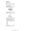
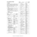
Paper transport in duplex printing (with AR-DU3/DU4 installed)
(1) Switchback operation and paper exit to the left tray
1) Paper transported from the fusing section is sent to the paper exit section of the machine.
2) When the male bin stacker (AR-MS1) or the finisher (AR-FN5) is installed, the paper entry gate solenoid (FGS) selects the paper entry
gate to discharge paper outside the machine.
3) The paper exit sensor (POD2) detects the rear edge of paper, and the paper exit motor (POM) is rotated reversely.
4) Paper is taken into the machine again, passed over the reverse gate, and transported to the duplex unit.
5) When duplex printing is made, the ADU gate solenoid switches to the upper side of the ADU paper exit gate to switch the paper path to
the ADU.
6) When paper is discharged to the left tray or when paper is transported to the console finisher (AR-FN7), the ADU gate solenoid
switches to the upper side of the ADU paper exit gate to switch the paper path to the ADU.
(2) Paper transport speed in duplex printing
The transport speed may be doubled in duplex printing depending on the paper position.
The positions of double speed are as follows:
1) From when the rear edge of paper passes the fusing section to when switchback operation is started.
2) From switchback operation, after the lead edge of paper passes APPD1, until a certain amount is transported.
3) After that, paper is stopped at the ADU paper feed position, and fed to the laser printer again.
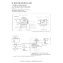
4.
Transport with AR-FN6 installed
The AR-FN6 is provided with the decurler to improve alignment capability of finishing.
The decurler makes decurling against curling of paper by means of the difference in rigidity of the upper roller (metal) and the lower roller
(sponge).
(sponge).
Metal
Sponge

