|
|
AR-M35 AR-M450 (serv.man8)
AR350 450 Series Basic Service Manual
Service Manual
|
54
|
6 MB
|
|
|
AR-M35 AR-M450 (serv.man9)
ARM350 450U N Version Service Manual
Service Manual
|
72
|
5.28 MB
|
|
|
AR-M35 AR-M450 (serv.man10)
Circuit Diagram
Service Manual
|
80
|
7.83 MB
|
|
|
AR-M35 AR-M450 (serv.man11)
Service Manual Section 1 - Product Outline, Congiguration, Specifications, Consumable Parts, External Views, Unpacking.
Service Manual
|
34
|
2.18 MB
|
|
|
AR-M35 AR-M450 (serv.man13)
Service Manual Section 3 - Electrical Section
Service Manual
|
12
|
686.99 KB
|
|
|
AR-M351N AR-M451N (serv.man4)
ARM351N-451N Service Manual
Service Manual
|
127
|
17.31 MB
|
|
|
AR-M351U AR-M451U (serv.man3)
Front Back Covers
Service Manual
|
9
|
2.62 MB
|
|
|
AR-M351U AR-M451U (serv.man4)
General
Service Manual
|
1
|
45 KB
|
|
|
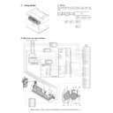
AR-M351U AR-M451U (serv.man5)
Configuration
Service Manual
|
4
|
153.04 KB
|
|
|
AR-M351U AR-M451U (serv.man6)
Specifications
Service Manual
|
9
|
113.49 KB
|
|
|
AR-M351U AR-M451U (serv.man7)
Consumable Parts
Service Manual
|
4
|
87.61 KB
|
|
|
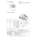
AR-M351U AR-M451U (serv.man8)
External Views Internal Structures.
Service Manual
|
8
|
476.72 KB
|
|
|
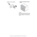
AR-M351U AR-M451U (serv.man9)
Unpacking and Installation
Service Manual
|
14
|
1.31 MB
|
|
|
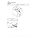
AR-M351U AR-M451U (serv.man10)
Maintenance details of following sections, (Maintenance System Table)
Service Manual
|
3
|
60.82 KB
|
|
|
AR-M351U AR-M451U (serv.man11)
Maintenance details of following sections, 1-Process
Service Manual
|
17
|
1.78 MB
|
|
|
AR-M351U AR-M451U (serv.man12)
Maintenance details of following sections, 2-Fuser, 3-Paper Feed
Service Manual
|
12
|
1.29 MB
|
|
|
AR-M351U AR-M451U (serv.man13)
Maintenance details of following sections, 4-Transport Paper exit reverse,
Service Manual
|
10
|
1.66 MB
|
|
|
AR-M351U AR-M451U (serv.man14)
Maintenance details of following sections, 5-Laser Scanner, 6-Scanner, 7-DSPF, 8-Operation Panel
Service Manual
|
23
|
2.37 MB
|
|
|
AR-M351U AR-M451U (serv.man15)
Maintenance details of following sections, 9-Filter, 10-Drive Section, 11-Power section, 12-PWB, 13-Fan Motor.
Service Manual
|
10
|
2.64 MB
|
|
|
AR-M351U AR-M451U (serv.man16)
Adjustments
Service Manual
|
17
|
1.78 MB
|
|
|
AR-M351U AR-M451U (serv.man17)
Simulations
Service Manual
|
88
|
887.33 KB
|
|
|
AR-M351U AR-M451U (serv.man18)
Machine Operation
Service Manual
|
3
|
137.33 KB
|
|
|
AR-M351U AR-M451U (serv.man19)
Trouble Codes
Service Manual
|
16
|
185.89 KB
|
|
|
AR-M351U AR-M451U (serv.man20)
Rom Version Up Method
Service Manual
|
5
|
261.26 KB
|
|
|
AR-M351U AR-M451U (serv.man21)
Electrical
Service Manual
|
23
|
253.27 KB
|

|
AR-M351U AR-M451U (serv.man22)
Complete Service Manual
Service Manual
|
|
14.49 MB
|
|
|
AR-M35 AR-M450 (serv.man32)
ARM350 450-Operation Manual (copy)
User Manual / Operation Manual
|
38
|
883.86 KB
|
|
|
AR-M35 AR-M450 (serv.man33)
ARP M350 450-Operation Manual (Printer)
User Manual / Operation Manual
|
8
|
178.32 KB
|
|
|
AR-M351N AR-M451N (serv.man6)
AR-FX12 (Fax Option) Operation Manual, when installed on AR-M351N and AR-M451N.
User Manual / Operation Manual
|
104
|
4.3 MB
|
|
|
AR-M351N AR-M451N (serv.man7)
AR-PK6 (PS Option) Printer Software Setup Guide, when installed on AR-M351N and AR-M451N.
User Manual / Operation Manual
|
16
|
2.2 MB
|
|
|
AR-M351N AR-M451N (serv.man8)
Software Setup Guide (for Printer).
User Manual / Operation Manual
|
24
|
2 MB
|
|
|
AR-M351N AR-M451N (serv.man9)
Operation Manual (for Key-Operator).
User Manual / Operation Manual
|
20
|
644.28 KB
|
|
|
AR-M351N AR-M451N (serv.man10)
Operation Manual (for General Information and Copier Operation).
User Manual / Operation Manual
|
127
|
9.1 MB
|

|
AR-M35 AR-M450
ARM350 450 Drivers for Mac OS 10.1 to 10.6. Requires ARPK1 PS Option. Mac OS
Drivers
|
|
16.9 MB
|

|
AR-M35 AR-M450 (serv.man2)
Mac OS X driver (for 10.1 to 10.3). Mac OS
Drivers
|
|
2.96 MB
|

|
AR-M35 AR-M450 (serv.man3)
Apple Mac OS 8 9 Driver Installer. Mac OS
Drivers
|
|
1.6 MB
|

|
AR-M35 AR-M450 (serv.man4)
PCL6 Driver Build 0708a. Windows Vista
Drivers
|
|
7.34 MB
|

|
AR-M35 AR-M450 (serv.man5)
PS Driver Build 0708a. Windows Vista
Drivers
|
|
6.08 MB
|

|
AR-M35 AR-M450 (serv.man6)
PCL6 Driver Build 0708a. Windows Vista
Drivers
|
|
6.67 MB
|

|
AR-M35 AR-M450 (serv.man110)
Win2K Combined PCL5e PCL6 PS Driver (Build 1.5J.010) supporting Win2K 2003 Server with WHQL. Windows 2000
Drivers
|
|
3.66 MB
|

|
AR-M35 AR-M450 (serv.man111)
Windows 2000 PCL5e driver version 4.0.0 build 071. Windows 2000
Drivers
|
|
1.14 MB
|

|
AR-M35 AR-M450 (serv.man112)
Windows 2000 PCL6 driver version 4.0.0 build 071. Windows 2000
Drivers
|
|
1.11 MB
|

|
AR-M35 AR-M450 (serv.man113)
Windows 2000 PCL6 driver version 2.2.0u build 067, which supports different first page in pamphlet mode. Windows 2000
Drivers
|
|
1.05 MB
|

|
AR-M35 AR-M450 (serv.man114)
Windows 2000 PCL5e driver version 2.2.0u build 067, which supports different first page in pamphlet mode. Windows 2000
Drivers
|
|
1.08 MB
|

|
AR-M35 AR-M450 (serv.man115)
Windows 2000 WHQL Certified Postscript PPD. Windows 2000
Drivers
|
|
35.2 KB
|

|
AR-M35 AR-M450 (serv.man116)
Windows 2000 WHQL Certified Postscript driver version 2.2.0 build 066. Windows 2000
Drivers
|
|
2.26 MB
|

|
AR-M35 AR-M450 (serv.man117)
Windows 2000 WHQL Certified PCL6 driver version 2.2.0 build 065. Windows 2000
Drivers
|
|
1.06 MB
|

|
AR-M35 AR-M450 (serv.man118)
Windows 2000 WHQL Certified PCL5e driver version 2.2.0 build 065. Windows 2000
Drivers
|
|
1.08 MB
|

|
AR-M35 AR-M450 (serv.man119)
Windows XP (64bit) PCL6 Driver. Windows XP
Drivers
|
|
7.35 MB
|

|
AR-M35 AR-M450 (serv.man120)
WinXP GPD Driver for WinXP x64 Edition. Version 1.0.0.9 Production Run Date 27 12 2005. Windows XP
Drivers
|
|
33.8 KB
|

|
AR-M35 AR-M450 (serv.man121)
WinXP Combined PCL5e PCL6 PS Driver (Build 1.5J.010) supporting Win2K 2003 Server with WHQL. Windows XP
Drivers
|
|
3.66 MB
|

|
AR-M35 AR-M450 (serv.man122)
Windows XP PCL5e driver version 4.0.0 build 071. Windows XP
Drivers
|
|
1.14 MB
|

|
AR-M35 AR-M450 (serv.man123)
Windows XP PCL6 driver version 4.0.0 build 071. Windows XP
Drivers
|
|
1.11 MB
|

|
AR-M35 AR-M450 (serv.man124)
Windows XP PCL6 driver version 2.2.0u build 067, which supports different first page in pamphlet mode. Windows XP
Drivers
|
|
1.05 MB
|

|
AR-M35 AR-M450 (serv.man125)
Windows XP PCL5e driver version 2.2.0u build 067, which supports different first page in pamphlet mode. Windows XP
Drivers
|
|
1.08 MB
|

|
AR-M35 AR-M450 (serv.man126)
Windows XP WHQL Certified POSTSCRIPT driver version 2.2.0 build 066. Windows XP
Drivers
|
|
2.26 MB
|

|
AR-M35 AR-M450 (serv.man127)
Windows XP WHQL Certified PCL6 driver version 2.2.0 build 065. Windows XP
Drivers
|
|
1.06 MB
|

|
AR-M35 AR-M450 (serv.man128)
Windows XP WHQL Certified PCL5e driver version 2.2.0 build 065. Windows XP
Drivers
|
|
1.08 MB
|

|
AR-M35 AR-M450 (serv.man129)
WinNT4.0 Combined PCL5e PCL6 PS Driver (Build 1.5J.010) supporting Win2K 2003 Server. Windows NT4
Drivers
|
|
3.63 MB
|

|
AR-M35 AR-M450 (serv.man130)
Windows NT PCL6 driver version 4.0.0 build 071. Windows NT4
Drivers
|
|
1.1 MB
|

|
AR-M35 AR-M450 (serv.man131)
Windows NT PCL5e driver version 4.0.0 build 071. Windows NT4
Drivers
|
|
1.13 MB
|

|
AR-M35 AR-M450 (serv.man132)
Windows NT PCL6 driver version 2.2.0u build 067, which supports different first page in pamphlet mode. Windows NT4
Drivers
|
|
1.05 MB
|

|
AR-M35 AR-M450 (serv.man133)
Windows NT PCL5e driver version 2.2.0u build 067, which supports different first page in pamphlet mode. Windows NT4
Drivers
|
|
1.08 MB
|

|
AR-M35 AR-M450 (serv.man134)
Windows NT4 Postscript PPD. Windows NT4
Drivers
|
|
179.57 KB
|

|
AR-M35 AR-M450 (serv.man135)
Windows NT4 PCL6 driver version 2.2.0 build 065. Windows NT4
Drivers
|
|
1.05 MB
|

|
AR-M35 AR-M450 (serv.man136)
Windows NT4 PCL5 driver version 2.2.0 build 065. Windows NT4
Drivers
|
|
1.07 MB
|

|
AR-M35 AR-M450 (serv.man137)
Windows ME PCL5e driver version 4.0.0 build 071. Windows ME
Drivers
|
|
1.29 MB
|

|
AR-M35 AR-M450 (serv.man138)
Windows ME PCL6 driver version 4.0.0 build 071. Windows ME
Drivers
|
|
1.29 MB
|

|
AR-M35 AR-M450 (serv.man139)
Windows ME PCL6 driver version 2.2.0u build 067, which supports different first page in pamphlet mode. Windows ME
Drivers
|
|
1.3 MB
|

|
AR-M35 AR-M450 (serv.man140)
Windows ME PCL5e driver version 2.2.0u build 067, which supports different first page in pamphlet mode. Windows ME
Drivers
|
|
1.3 MB
|

|
AR-M35 AR-M450 (serv.man141)
Windows ME WHQL Certified Postscript PPD. Windows ME
Drivers
|
|
299.95 KB
|

|
AR-M35 AR-M450 (serv.man142)
Windows ME WHQL Certified Postscript driver version 2.2.0 build 065. Windows ME
Drivers
|
|
2.63 MB
|

|
AR-M35 AR-M450 (serv.man143)
Windows ME WHQL Certified PCL6 driver version 2.2.0 build 065. Windows ME
Drivers
|
|
1.3 MB
|

|
AR-M35 AR-M450 (serv.man144)
Windows ME WHQL Certified PCL5e driver version 2.2.0 build 065. Windows ME
Drivers
|
|
1.3 MB
|

|
AR-M35 AR-M450 (serv.man145)
Windows ME PCL5e driver version 4.0.0 build 071. Windows 98
Drivers
|
|
1.29 MB
|

|
AR-M35 AR-M450 (serv.man146)
Windows ME PCL6 driver version 4.0.0 build 071. Windows 98
Drivers
|
|
1.29 MB
|

|
AR-M35 AR-M450 (serv.man147)
Windows 98 PCL6 driver version 2.2.0u build 067, which supports different first page in pamphlet mode. Windows 98
Drivers
|
|
1.3 MB
|

|
AR-M35 AR-M450 (serv.man148)
Windows 98 PCL5e driver version 2.2.0u build 067, which supports different first page in pamphlet mode. Windows 98
Drivers
|
|
1.3 MB
|

|
AR-M35 AR-M450 (serv.man149)
Windows 95 98 Postscript PPD. Windows 98
Drivers
|
|
299.95 KB
|

|
AR-M35 AR-M450 (serv.man150)
Windows 95 98 Postscript driver version 2.2.0 build 065. Windows 98
Drivers
|
|
2.63 MB
|

|
AR-M35 AR-M450 (serv.man151)
Windows 95 98 PCL6 driver version 2.2.0 build 065. Windows 98
Drivers
|
|
1.3 MB
|

|
AR-M35 AR-M450 (serv.man152)
Windows 95 98 PCL5e driver version 2.2.0 build 065. Windows 98
Drivers
|
|
1.3 MB
|

|
AR-M351N AR-M451N
ARM351 451 Mac PPD for MacOS 10.5. Mac OS
Drivers
|
|
1.63 MB
|

|
AR-M351N AR-M451N (serv.man53)
Windows Server 2008 64-bit PCL6 Print Driver supporting WHQL (Windows 64bit OS) Version 01.00.16.002. Windows Vista
Drivers
|
|
12.59 MB
|

|
AR-M351N AR-M451N (serv.man54)
ARM236 256 276 316 351 451 550 620 700 PS Driver for Windows Vista 64Bit. Version 801a WHQL signed. Windows Vista
Drivers
|
|
10.76 MB
|

|
AR-M351N AR-M451N (serv.man55)
Windows Vista PCL6 64 Bit Driver. Windows Vista
Drivers
|
|
5.86 MB
|

|
AR-M351N AR-M451N (serv.man56)
Windows Vista PCL6 Driver. This diver can be used in conjunction with 64 Bit printer driver. Windows Vista
Drivers
|
|
5.17 MB
|

|
AR-M351N AR-M451N (serv.man57)
AR-P20_PCFAX_0701a_EnglishUS_Vista 32bit. Windows Vista
Drivers
|
|
15.96 MB
|

|
AR-M351N AR-M451N (serv.man58)
Windows Vista PCL6 Driver. Windows Vista
Drivers
|
|
2.94 MB
|

|
AR-M351N AR-M451N (serv.man59)
Windows Vista PCL5e Driver. Windows Vista
Drivers
|
|
2.29 MB
|

|
AR-M351N AR-M451N (serv.man60)
Windows 2000 PCL6 64 Bit Driver. Windows 2000
Drivers
|
|
5.86 MB
|

|
AR-M351N AR-M451N (serv.man61)
Windows 2000 PCL6 Driver. This diver can be used in conjunction with 64 Bit printer driver. Windows 2000
Drivers
|
|
5.17 MB
|

|
AR-M351N AR-M451N (serv.man62)
CD Ver 2.03 - Production Run Date 09 11 2005. This Driver is WHQL compliant. Windows 2000
Drivers
|
|
2.87 MB
|

|
AR-M351N AR-M451N (serv.man63)
CD Ver 2.03 - Production Run Date 09 11 2005. This Driver is WHQL compliant. Windows 2000
Drivers
|
|
2.21 MB
|

|
AR-M351N AR-M451N (serv.man64)
Win2K PCL6 Driver (Ver 2.00d.001) From Production Run Date 31 10 2005. Windows 2000
Drivers
|
|
2.86 MB
|

|
AR-M351N AR-M451N (serv.man65)
Win2K PCL5e Driver (Ver 2.00d.001) From Production Run Date 31 10 2005. Windows 2000
Drivers
|
|
2.2 MB
|

|
AR-M351N AR-M451N (serv.man66)
AR-M351N-M351U-M451N-M451U PCL6 Driver for Win2K, v2.01(v2.00a.004) Supporting Win2K 2003 Server WHQL (Including 'Add Printer' Wizard support). Windows 2000
Drivers
|
|
2.87 MB
|

|
AR-M351N AR-M451N (serv.man67)
AR-M351N-M351U-M451N-M451U PCL5e Driver for Win2K, v2.01(v2.00a.004) Supporting Win2K 2003 Server WHQL (Including 'Add Printer' Wizard support). Windows 2000
Drivers
|
|
2.21 MB
|

|
AR-M351N AR-M451N (serv.man68)
PCL5e Driver for Win2K v2.01 (01.21.00.18) Supporting Win2K 2003 Server WHQL. Change details enclosed. Windows 2000
Drivers
|
|
2.21 MB
|

|
AR-M351N AR-M451N (serv.man69)
01.00.14.10 - CD Ver 1.10). Windows 2000
Drivers
|
|
2.84 MB
|

|
AR-M351N AR-M451N (serv.man70)
01.00.14.10 - CD Ver 1.10). Windows 2000
Drivers
|
|
2.18 MB
|

|
AR-M351N AR-M451N (serv.man71)
ARM236 256 276 316 351 451 550 620 700 PS Driver for Windows XP 64Bit. Version 801a WHQL signed. Windows XP
Drivers
|
|
10.76 MB
|

|
AR-M351N AR-M451N (serv.man72)
Windows XP PCL6 64 Bit Driver. Windows XP
Drivers
|
|
5.86 MB
|

|
AR-M351N AR-M451N (serv.man73)
Windows XP PCL6 Driver. This diver can be used in conjunction with 64 Bit printer driver. Windows XP
Drivers
|
|
5.17 MB
|

|
AR-M351N AR-M451N (serv.man74)
Production Run Date 27 12 2005. Windows XP
Drivers
|
|
31.85 KB
|

|
AR-M351N AR-M451N (serv.man75)
CD Ver 2.03 - Production Run Date 09 11 2005. This Driver is WHQL compliant. Windows XP
Drivers
|
|
2.87 MB
|

|
AR-M351N AR-M451N (serv.man76)
CD Ver 2.03 - Production Run Date 09 11 2005. This Driver is WHQL compliant. Windows XP
Drivers
|
|
2.21 MB
|

|
AR-M351N AR-M451N (serv.man77)
WinXP PCL6 Driver (Ver 2.00d.001) From Production Run Date 31 10 2005. Windows XP
Drivers
|
|
2.86 MB
|

|
AR-M351N AR-M451N (serv.man78)
WinXP PCL5e Driver (Ver 2.00d.001) From Production Run Date 31 10 2005. Windows XP
Drivers
|
|
2.2 MB
|

|
AR-M351N AR-M451N (serv.man79)
AR-M351N-M351U-M451N-M451U PCL6 Driver for WinXP, v2.01(v2.00a.004) Supporting Win2K 2003 Server WHQL (Including 'Add Printer' Wizard support). Windows XP
Drivers
|
|
2.87 MB
|

|
AR-M351N AR-M451N (serv.man80)
AR-M351N-M351U-M451N-M451U PCL5e Driver for WinXP, v2.01(v2.00a.004) Supporting Win2K 2003 Server WHQL (Including 'Add Printer' Wizard support). Windows XP
Drivers
|
|
2.21 MB
|

|
AR-M351N AR-M451N (serv.man81)
PCL6 Driver for WinXP v2.01 (01.21.01.18) Supporting Win2K 2003 Server WHQL. Change details enclosed. Windows XP
Drivers
|
|
2.87 MB
|

|
AR-M351N AR-M451N (serv.man82)
PCL5e Driver for WinXP v2.01 (01.21.00.18) Supporting Win2K 2003 Server WHQL. Change details enclosed. Windows XP
Drivers
|
|
2.21 MB
|

|
AR-M351N AR-M451N (serv.man83)
01.00.14.10 - CD Ver 1.10). Windows XP
Drivers
|
|
2.84 MB
|

|
AR-M351N AR-M451N (serv.man84)
01.00.14.10 - CD Ver 1.10). Windows XP
Drivers
|
|
2.18 MB
|

|
AR-M351N AR-M451N (serv.man85)
CD Ver 2.03 - Production Run Date 09 11 2005. This Driver is WHQL compliant. Windows NT4
Drivers
|
|
2.79 MB
|

|
AR-M351N AR-M451N (serv.man86)
CD Ver 2.03 - Production Run Date 09 11 2005. This Driver is WHQL compliant. Windows NT4
Drivers
|
|
2.21 MB
|

|
AR-M351N AR-M451N (serv.man87)
WinNT4.0 PCL6 Driver (Ver 2.00d.001) From Production Run Date 31 10 2005. Windows NT4
Drivers
|
|
2.79 MB
|

|
AR-M351N AR-M451N (serv.man88)
WinNT4.0 PCL5e Driver (Ver 2.00d.001) From Production Run Date 31 10 2005. Windows NT4
Drivers
|
|
2.21 MB
|

|
AR-M351N AR-M451N (serv.man89)
AR-M351N-M351U-M451N-M451U PCL6 Driver for WinNT4.0, v2.01(v2.00a.004) Supporting Win2K 2003 Server. Windows NT4
Drivers
|
|
2.79 MB
|

|
AR-M351N AR-M451N (serv.man90)
AR-M351N-M351U-M451N-M451U PCL5e Driver for WinNT4.0, v2.01(v2.00a.004) Supporting Win2K 2003 Server. Windows NT4
Drivers
|
|
2.21 MB
|

|
AR-M351N AR-M451N (serv.man91)
PCL6 Driver for WinNT4.0 v2.01 (01.21.01.18) Supporting Win2K 2003 Server. Change details enclosed. Windows NT4
Drivers
|
|
2.79 MB
|

|
AR-M351N AR-M451N (serv.man92)
PCL5e Driver for WinNT4.0 v2.01 (01.21.00.18) Supporting Win2K 2003 Server. Change details enclosed. Windows NT4
Drivers
|
|
2.21 MB
|

|
AR-M351N AR-M451N (serv.man93)
01.00.14.10 - CD Ver 1.10). Windows NT4
Drivers
|
|
2.78 MB
|

|
AR-M351N AR-M451N (serv.man94)
01.00.14.10 - CD Ver 1.10). Windows NT4
Drivers
|
|
2.2 MB
|

|
AR-M351N AR-M451N (serv.man95)
CD Ver 2.03 - Production Run Date 09 11 2005. This Driver is WHQL compliant. Windows ME
Drivers
|
|
2.89 MB
|

|
AR-M351N AR-M451N (serv.man96)
CD Ver 2.03 - Production Run Date 09 11 2005. This Driver is WHQL compliant. Windows ME
Drivers
|
|
2.59 MB
|

|
AR-M351N AR-M451N (serv.man97)
WinMe PCL6 Driver (Ver 2.00d.001) From Production Run Date 31 10 2005. Windows ME
Drivers
|
|
2.89 MB
|

|
AR-M351N AR-M451N (serv.man98)
WinMe PCL5e Driver (Ver 2.00d.001) From Production Run Date 31 10 2005. Windows ME
Drivers
|
|
2.59 MB
|

|
AR-M351N AR-M451N (serv.man99)
AR-M351N-M351U-M451N-M451U PCL6 Driver for WinMe, v2.01(v2.00a.004) Supporting Win2K 2003 Server. Windows ME
Drivers
|
|
2.89 MB
|

|
AR-M351N AR-M451N (serv.man100)
AR-M351N-M351U-M451N-M451U PCL5e Driver for WinMe, v2.01(v2.00a.004) Supporting Win2K 2003 Server. Windows ME
Drivers
|
|
2.59 MB
|

|
AR-M351N AR-M451N (serv.man101)
PCL6 Driver for WinME v2.01 (01.21.01.18) Supporting Win2K 2003 Server. Change details enclosed. Windows ME
Drivers
|
|
2.89 MB
|

|
AR-M351N AR-M451N (serv.man102)
PCL5e Driver for WinME v2.01 (01.21.00.18) Supporting Win2K 2003 Server. Change details enclosed. Windows ME
Drivers
|
|
2.59 MB
|

|
AR-M351N AR-M451N (serv.man103)
01.00.14.10 - CD Ver 1.10). Windows ME
Drivers
|
|
2.88 MB
|

|
AR-M351N AR-M451N (serv.man104)
01.00.14.10 - CD Ver 1.10). Windows ME
Drivers
|
|
2.58 MB
|

|
AR-M351N AR-M451N (serv.man105)
CD Ver 2.03 - Production Run Date 09 11 2005. This Driver is WHQL compliant. Windows 98
Drivers
|
|
2.92 MB
|

|
AR-M351N AR-M451N (serv.man106)
CD Ver 2.03 - Production Run Date 09 11 2005. This Driver is WHQL compliant. Windows 98
Drivers
|
|
2.62 MB
|

|
AR-M351N AR-M451N (serv.man107)
Win9x PCL6 Driver (Ver 2.00d.001) From Production Run Date 31 10 2005. Windows 98
Drivers
|
|
2.92 MB
|

|
AR-M351N AR-M451N (serv.man108)
Win9x PCL5e Driver (Ver 2.00d.001) From Production Run Date 31 10 2005. Windows 98
Drivers
|
|
2.62 MB
|

|
AR-M351N AR-M451N (serv.man109)
AR-M351N-M351U-M451N-M451U PCL6 Driver for Win9X, v2.01(v2.00a.004) Supporting Win2K 2003 Server. Windows 98
Drivers
|
|
2.92 MB
|

|
AR-M351N AR-M451N (serv.man110)
AR-M351N-M351U-M451N-M451U PCL5e Driver for Win9X, v2.01(v2.00a.004) Supporting Win2K 2003 Server. Windows 98
Drivers
|
|
2.62 MB
|

|
AR-M351N AR-M451N (serv.man111)
PCL6 Driver for Win9X v2.01 (01.21.01.18) Supporting Win2K 2003 Server. Change details enclosed. Windows 98
Drivers
|
|
2.92 MB
|

|
AR-M351N AR-M451N (serv.man112)
PCL5e Driver for Win9X v2.01 (01.21.00.18) Supporting Win2K 2003 Server. Change details enclosed. Windows 98
Drivers
|
|
2.62 MB
|

|
AR-M351N AR-M451N (serv.man113)
01.00.14.10 - CD Ver 1.10). Windows 98
Drivers
|
|
2.91 MB
|

|
AR-M351N AR-M451N (serv.man114)
01.00.14.10 - CD Ver 1.10). Windows 98
Drivers
|
|
2.61 MB
|

|
AR-M351U AR-M451U
ARM351 451 Mac PPD for MacOS 10.5. Mac OS
Drivers
|
|
1.63 MB
|

|
AR-M351U AR-M451U (serv.man59)
ARM236 256 276 316 351 451 550 620 700 PS Driver for Windows Vista 64Bit. Version 801a WHQL signed. Windows Vista
Drivers
|
|
10.76 MB
|

|
AR-M351U AR-M451U (serv.man60)
Windows Vista PCL6 64 Bit Driver. Windows Vista
Drivers
|
|
5.86 MB
|

|
AR-M351U AR-M451U (serv.man61)
Windows Vista PCL6 Driver. This diver can be used in conjunction with 64 Bit printer driver. Windows Vista
Drivers
|
|
5.17 MB
|

|
AR-M351U AR-M451U (serv.man62)
Windows Vista PCL6 Driver. Windows Vista
Drivers
|
|
2.94 MB
|

|
AR-M351U AR-M451U (serv.man63)
Windows Vista PCL5e Driver. Windows Vista
Drivers
|
|
2.29 MB
|

|
AR-M351U AR-M451U (serv.man64)
Windows 2000 PCL6 64 Bit Driver. Windows 2000
Drivers
|
|
5.86 MB
|

|
AR-M351U AR-M451U (serv.man65)
Windows 2000 PCL6 Driver. This diver can be used in conjunction with 64 Bit printer driver. Windows 2000
Drivers
|
|
5.17 MB
|

|
AR-M351U AR-M451U (serv.man66)
CD Ver 2.03 - Production Run Date 09 11 2005. This Driver is WHQL compliant. Windows 2000
Drivers
|
|
2.87 MB
|

|
AR-M351U AR-M451U (serv.man67)
CD Ver 2.03 - Production Run Date 09 11 2005. This Driver is WHQL compliant. Windows 2000
Drivers
|
|
2.21 MB
|

|
AR-M351U AR-M451U (serv.man68)
Win2K PCL6 Driver (Ver 2.00d.001) From Production Run Date 31 10 2005. Windows 2000
Drivers
|
|
2.86 MB
|

|
AR-M351U AR-M451U (serv.man69)
Win2K PCL5e Driver (Ver 2.00d.001) From Production Run Date 31 10 2005. Windows 2000
Drivers
|
|
2.2 MB
|

|
AR-M351U AR-M451U (serv.man70)
AR-M351N-M351U-M451N-M451U PPD Driver for Win2K, v2.01(v2.00a.004) Supporting Win2K 2003 Server WHQL (Including 'Add Printer' Wizard support). Windows 2000
Drivers
|
|
17.1 KB
|

|
AR-M351U AR-M451U (serv.man71)
AR-M351N-M351U-M451N-M451U PCL6 Driver for Win2K, v2.01(v2.00a.004) Supporting Win2K 2003 Server WHQL (Including 'Add Printer' Wizard support). Windows 2000
Drivers
|
|
2.87 MB
|

|
AR-M351U AR-M451U (serv.man72)
AR-M351N-M351U-M451N-M451U PCL5e Driver for Win2K, v2.01(v2.00a.004) Supporting Win2K 2003 Server WHQL (Including 'Add Printer' Wizard support). Windows 2000
Drivers
|
|
2.21 MB
|

|
AR-M351U AR-M451U (serv.man73)
ARM236 256 276 316 351 451 550 620 700 PS Driver for Windows XP 64Bit. Version 801a WHQL signed. Windows XP
Drivers
|
|
10.76 MB
|

|
AR-M351U AR-M451U (serv.man74)
Windows XP PCL6 64 Bit Driver. Windows XP
Drivers
|
|
5.86 MB
|

|
AR-M351U AR-M451U (serv.man75)
Windows XP PCL6 Driver. This diver can be used in conjunction with 64 Bit printer driver. Windows XP
Drivers
|
|
5.17 MB
|

|
AR-M351U AR-M451U (serv.man76)
Production Run Date 27 12 2005. Windows XP
Drivers
|
|
31.85 KB
|

|
AR-M351U AR-M451U (serv.man77)
CD Ver 2.03 - Production Run Date 09 11 2005. This Driver is WHQL compliant. Windows XP
Drivers
|
|
2.87 MB
|

|
AR-M351U AR-M451U (serv.man78)
CD Ver 2.03 - Production Run Date 09 11 2005. This Driver is WHQL compliant. Windows XP
Drivers
|
|
2.21 MB
|

|
AR-M351U AR-M451U (serv.man79)
WinXP PCL6 Driver (Ver 2.00d.001) From Production Run Date 31 10 2005. Windows XP
Drivers
|
|
2.86 MB
|

|
AR-M351U AR-M451U (serv.man80)
WinXP PCL5e Driver (Ver 2.00d.001) From Production Run Date 31 10 2005. Windows XP
Drivers
|
|
2.2 MB
|

|
AR-M351U AR-M451U (serv.man81)
AR-M351N-M351U-M451N-M451U PPD Driver for WinXP, v2.01(v2.00a.004) Supporting Win2K 2003 Server WHQL (Including 'Add Printer' Wizard support). Windows XP
Drivers
|
|
17.1 KB
|

|
AR-M351U AR-M451U (serv.man82)
AR-M351N-M351U-M451N-M451U PCL6 Driver for WinXP, v2.01(v2.00a.004) Supporting Win2K 2003 Server WHQL (Including 'Add Printer' Wizard support). Windows XP
Drivers
|
|
2.87 MB
|

|
AR-M351U AR-M451U (serv.man83)
AR-M351N-M351U-M451N-M451U PCL5e Driver for WinXP, v2.01(v2.00a.004) Supporting Win2K 2003 Server WHQL (Including 'Add Printer' Wizard support). Windows XP
Drivers
|
|
2.21 MB
|

|
AR-M351U AR-M451U (serv.man84)
CD Ver 2.03 - Production Run Date 09 11 2005. This Driver is WHQL compliant. Windows NT4
Drivers
|
|
2.79 MB
|

|
AR-M351U AR-M451U (serv.man85)
CD Ver 2.03 - Production Run Date 09 11 2005. This Driver is WHQL compliant. Windows NT4
Drivers
|
|
2.21 MB
|

|
AR-M351U AR-M451U (serv.man86)
WinNT4.0 PCL6 Driver (Ver 2.00d.001) From Production Run Date 31 10 2005. Windows NT4
Drivers
|
|
2.79 MB
|

|
AR-M351U AR-M451U (serv.man87)
WinNT4.0 PCL5e Driver (Ver 2.00d.001) From Production Run Date 31 10 2005. Windows NT4
Drivers
|
|
2.21 MB
|

|
AR-M351U AR-M451U (serv.man88)
AR-M351N-M351U-M451N-M451U PPD Driver for WinNT4.0, v2.01(v2.00a.004) Supporting Win2K 2003 Server. Windows NT4
Drivers
|
|
89.49 KB
|

|
AR-M351U AR-M451U (serv.man89)
AR-M351N-M351U-M451N-M451U PCL6 Driver for WinNT4.0, v2.01(v2.00a.004) Supporting Win2K 2003 Server. Windows NT4
Drivers
|
|
2.79 MB
|

|
AR-M351U AR-M451U (serv.man90)
AR-M351N-M351U-M451N-M451U PCL5e Driver for WinNT4.0, v2.01(v2.00a.004) Supporting Win2K 2003 Server. Windows NT4
Drivers
|
|
2.21 MB
|

|
AR-M351U AR-M451U (serv.man91)
CD Ver 2.03 - Production Run Date 09 11 2005. This Driver is WHQL compliant. Windows ME
Drivers
|
|
2.89 MB
|

|
AR-M351U AR-M451U (serv.man92)
CD Ver 2.03 - Production Run Date 09 11 2005. This Driver is WHQL compliant. Windows ME
Drivers
|
|
2.59 MB
|

|
AR-M351U AR-M451U (serv.man93)
WinMe PCL6 Driver (Ver 2.00d.001) From Production Run Date 31 10 2005. Windows ME
Drivers
|
|
2.89 MB
|

|
AR-M351U AR-M451U (serv.man94)
WinMe PCL5e Driver (Ver 2.00d.001) From Production Run Date 31 10 2005. Windows ME
Drivers
|
|
2.59 MB
|

|
AR-M351U AR-M451U (serv.man95)
AR-M351N-M351U-M451N-M451U PPD Driver for WinMe, v2.01(v2.00a.004) Supporting Win2K 2003 Server. Windows ME
Drivers
|
|
171.99 KB
|

|
AR-M351U AR-M451U (serv.man96)
AR-M351N-M351U-M451N-M451U PCL6 Driver for WinMe, v2.01(v2.00a.004) Supporting Win2K 2003 Server. Windows ME
Drivers
|
|
2.89 MB
|

|
AR-M351U AR-M451U (serv.man97)
AR-M351N-M351U-M451N-M451U PCL5e Driver for WinMe, v2.01(v2.00a.004) Supporting Win2K 2003 Server. Windows ME
Drivers
|
|
2.59 MB
|

|
AR-M351U AR-M451U (serv.man98)
CD Ver 2.03 - Production Run Date 09 11 2005. This Driver is WHQL compliant. Windows 98
Drivers
|
|
2.92 MB
|

|
AR-M351U AR-M451U (serv.man99)
CD Ver 2.03 - Production Run Date 09 11 2005. This Driver is WHQL compliant. Windows 98
Drivers
|
|
2.62 MB
|

|
AR-M351U AR-M451U (serv.man100)
Win9x PCL6 Driver (Ver 2.00d.001) From Production Run Date 31 10 2005. Windows 98
Drivers
|
|
2.92 MB
|

|
AR-M351U AR-M451U (serv.man101)
Win9x PCL5e Driver (Ver 2.00d.001) From Production Run Date 31 10 2005. Windows 98
Drivers
|
|
2.62 MB
|

|
AR-M351U AR-M451U (serv.man102)
AR-M351N-M351U-M451N-M451U PPD Driver for Win9X, v2.01(v2.00a.004) Supporting Win2K 2003 Server. Windows 98
Drivers
|
|
171.99 KB
|

|
AR-M351U AR-M451U (serv.man103)
AR-M351N-M351U-M451N-M451U PCL6 Driver for Win9X, v2.01(v2.00a.004) Supporting Win2K 2003 Server. Windows 98
Drivers
|
|
2.92 MB
|

|
AR-M351U AR-M451U (serv.man104)
AR-M351N-M351U-M451N-M451U PCL5e Driver for Win9X, v2.01(v2.00a.004) Supporting Win2K 2003 Server. Windows 98
Drivers
|
|
2.62 MB
|

|
AR-M35 AR-M450 (serv.man153)
PCL6 Driver Build 0708a. Windows Vista
Drivers
|
|
7.34 MB
|

|
AR-M35 AR-M450 (serv.man154)
PS Driver Build 0708a. Windows Vista
Drivers
|
|
6.08 MB
|

|
AR-M35 AR-M450 (serv.man155)
PCL6 Driver Build 0708a. Windows Vista
Drivers
|
|
6.67 MB
|
|
|
AR-M35 AR-M450 (serv.man14)
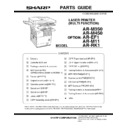
Revised Parts Guide
Service Manual / Parts Guide
|
30
|
1.08 MB
|
|
|
AR-M35 AR-M450 (serv.man15)
Rear frame section 2, 17 - Packing material accessories.
Service Manual / Parts Guide
|
8
|
458.76 KB
|
|
|
AR-M35 AR-M450 (serv.man16)
Information of parts change to sections 7-Fusing Unit, 8-Delivery Turn Over Unit, 12-Controller Box Unit.
Service Manual / Parts Guide
|
8
|
639.72 KB
|
|
|
AR-M35 AR-M450 (serv.man17)
Informationof parts changes to sections 1 Exteriors, 5 TC unit, 6 Cassette paper feeder, 7 Fusing unit, 8 Delivery turn over unit, 14 Rear frame section 1, 15 Rear frame section 2, 16 Cassette unit, 17 Packing material accessories.
Service Manual / Parts Guide
|
20
|
1.33 MB
|
|
|
AR-M35 AR-M450 (serv.man18)
Packing material accessories
Service Manual / Parts Guide
|
6
|
134.79 KB
|
|
|
AR-M35 AR-M450 (serv.man19)
Cassette paper feeder, 8 - Delivery turn over unit.
Service Manual / Parts Guide
|
5
|
379.48 KB
|
|
|
AR-M35 AR-M450 (serv.man20)
Controller Box Unit
Service Manual / Parts Guide
|
4
|
244.14 KB
|
|
|
AR-M35 AR-M450 (serv.man21)
Main drive unit, 7 - Fusing unit, 8 - Delivery turn over unit
Service Manual / Parts Guide
|
7
|
598.87 KB
|
|
|
AR-M35 AR-M450 (serv.man22)
Delivery Turn Over Unit, 14 - Rear Frame Section 1, 15 - Rear Frame Section 2.
Service Manual / Parts Guide
|
8
|
717.05 KB
|
|
|
AR-M35 AR-M450 (serv.man23)
Process unit, 12 - Controller box unit
Service Manual / Parts Guide
|
5
|
383.93 KB
|
|
|
AR-M35 AR-M450 (serv.man24)
Power supply unit, 14 - Rear frame section 1.
Service Manual / Parts Guide
|
4
|
354.43 KB
|
|
|
AR-M35 AR-M450 (serv.man25)
Left Door Unit, 7 - Fusing Unit, 12 - Controller Box Unit, 14 - Rear Frame Section 1, 15 - Rear Frame Section 2, 16 - Cassette Unit.
Service Manual / Parts Guide
|
13
|
1.05 MB
|
|
|
AR-M35 AR-M450 (serv.man26)
Fusing Unit, 8 - Delivery Turn Over Unit
Service Manual / Parts Guide
|
5
|
395.8 KB
|
|
|
AR-M35 AR-M450 (serv.man27)
Information of Parts changes, sections 12-Controller Box, 15-Rear Frame Section 2
Service Manual / Parts Guide
|
5
|
501.43 KB
|
|
|
AR-M35 AR-M450 (serv.man28)
11 Developer unit.
Service Manual / Parts Guide
|
3
|
140.92 KB
|
|
|
AR-M35 AR-M450 (serv.man29)
Update to the parts Guide November 04-The following sections have been updated, 4-Main Drive Unit, 6-Cassette Paper Feed, 7-Fusing Unit, 10-Process Unit, 14-Rear Frame Section 1, 17-Packing Material Accessories
Service Manual / Parts Guide
|
17
|
1.03 MB
|
|
|
AR-M35 AR-M450 (serv.man30)
Update to the parts guide October 04-The following sections have been updated, 1-Exteriors, 2-Left Door Unit, 3 PS Roller Unit, 12-Controller Box Unit, 14-Rear Frame Section.
Service Manual / Parts Guide
|
13
|
846.97 KB
|
|
|
AR-M35 AR-M450 (serv.man31)
ARM350 450U N Version Parts Guide
Service Manual / Parts Guide
|
12
|
295.5 KB
|
|
|
AR-M351N AR-M451N (serv.man5)
April 10
Service Manual / Parts Guide
|
93
|
4.54 MB
|
|
|
AR-M351U AR-M451U (serv.man23)
April 10
Service Manual / Parts Guide
|
93
|
4.54 MB
|
|
|
AR-M351N AR-M451N (serv.man3)
FIX TO INCREASE THE MARGIN THAT THE FAN MOTOR FASTENER WILL NOT BECOME STRIPPED
Service Manual / Specification
|
2
|
41.49 KB
|
|
|
AR-M351U AR-M451U (serv.man2)
General Specifications taken from Service Manual.
Service Manual / Specification
|
9
|
113.49 KB
|
|
|
AR-M35 AR-M450 (serv.man55)
PARTS GUIDE CORRECTION
Service Manual / Technical Bulletin
|
1
|
15.49 KB
|
|
|
AR-M35 AR-M450 (serv.man56)
ARE-902 SMUDGY IMAGE RECEPTION RESULTING FROM INCOMPLETE MG ROLLER ROTATION
Service Manual / Technical Bulletin
|
2
|
69.87 KB
|
|
|
AR-M35 AR-M450 (serv.man57)
051-Change to new type flash ROM (ELEM)
Service Manual / Technical Bulletin
|
2
|
140.54 KB
|
|
|
AR-M35 AR-M450 (serv.man58)
ROM upgrade 18
Service Manual / Technical Bulletin
|
2
|
10.33 KB
|
|
|
AR-M35 AR-M450 (serv.man59)
AC DC Board Change.
Service Manual / Technical Bulletin
|
9
|
608.61 KB
|
|
|
AR-M35 AR-M450 (serv.man60)
Change in the MFP board.
Service Manual / Technical Bulletin
|
5
|
393.74 KB
|
|
|
AR-M35 AR-M450 (serv.man61)
Reduction in E7-11 problem.
Service Manual / Technical Bulletin
|
2
|
31.74 KB
|
|
|
AR-M35 AR-M450 (serv.man62)
045-Adjustment required when the CIS unit or the CIS pwb is replaced.
Service Manual / Technical Bulletin
|
1
|
8.36 KB
|
|
|
AR-M35 AR-M450 (serv.man63)
To prevent abnormal noise from the fan of delivery turnover unit
Service Manual / Technical Bulletin
|
1
|
132.81 KB
|
|
|
AR-M35 AR-M450 (serv.man64)
L6-10 POLYGON MOTOR LOCK
Service Manual / Technical Bulletin
|
1
|
180.7 KB
|
|
|
AR-M35 AR-M450 (serv.man65)
The improvement for paper jam at delivery turn over unit
Service Manual / Technical Bulletin
|
2
|
88.53 KB
|
|
|
AR-M35 AR-M450 (serv.man66)
Preventing fixing unit from dropping
Service Manual / Technical Bulletin
|
2
|
157.05 KB
|
|
|
AR-M35 AR-M450 (serv.man67)
Procedures for replacement of the LSU unit
Service Manual / Technical Bulletin
|
3
|
306.42 KB
|
|
|
AR-M35 AR-M450 (serv.man68)
Improvement in lead edge skew caused by warp of the transfer front PG
Service Manual / Technical Bulletin
|
1
|
97.99 KB
|
|
|
AR-M35 AR-M450 (serv.man69)
Improved strength PS coupling
Service Manual / Technical Bulletin
|
1
|
64.92 KB
|
|
|
AR-M35 AR-M450 (serv.man70)
Duct support plate changed and duct support cover added
Service Manual / Technical Bulletin
|
1
|
31.21 KB
|
|
|
AR-M35 AR-M450 (serv.man71)
Parts change to separator pawl solenoid and side plate
Service Manual / Technical Bulletin
|
1
|
12.85 KB
|
|
|
AR-M35 AR-M450 (serv.man72)
The leading edge shape of the Separation Pawl has changed
Service Manual / Technical Bulletin
|
2
|
117.01 KB
|
|
|
AR-M35 AR-M450 (serv.man73)
Flash ROM version upgrade procedure (Revised)
Service Manual / Technical Bulletin
|
3
|
71.65 KB
|
|
|
AR-M35 AR-M450 (serv.man74)
Restraint on CE-00 trouble
Service Manual / Technical Bulletin
|
2
|
23.69 KB
|
|
|
AR-M35 AR-M450 (serv.man75)
ROM upgrade
Service Manual / Technical Bulletin
|
6
|
563.54 KB
|
|
|
AR-M35 AR-M450 (serv.man76)
Supply of additional material
Service Manual / Technical Bulletin
|
3
|
145.72 KB
|
|
|
AR-M35 AR-M450 (serv.man77)
Updated ROM version
Service Manual / Technical Bulletin
|
7
|
279.85 KB
|
|
|
AR-M35 AR-M450 (serv.man78)
Parts change information
Service Manual / Technical Bulletin
|
2
|
59.47 KB
|
|
|
AR-M35 AR-M450 (serv.man79)
Cautions when obtaining product keys
Service Manual / Technical Bulletin
|
1
|
21.28 KB
|
|
|
AR-M35 AR-M450 (serv.man80)
Parts change information
Service Manual / Technical Bulletin
|
2
|
35.6 KB
|
|
|
AR-M35 AR-M450 (serv.man81)
ARFN6 F1-87 ERROR
Service Manual / Technical Bulletin
|
2
|
504.94 KB
|
|
|
AR-M35 AR-M450 (serv.man82)
Paper jam in duplex mode from LCC tray of ARD13
Service Manual / Technical Bulletin
|
1
|
559.12 KB
|
|
|
AR-M35 AR-M450 (serv.man83)
Revision of the Service Manual (How to read the serial number of a developer cartridge)
Service Manual / Technical Bulletin
|
1
|
43.76 KB
|
|
|
AR-M35 AR-M450 (serv.man84)
Paper jam - MPFDNTD - from ARD13 14
Service Manual / Technical Bulletin
|
1
|
66.07 KB
|
|
|
AR-M35 AR-M450 (serv.man85)
Improving toner dispensing from toner cartridges
Service Manual / Technical Bulletin
|
1
|
39.86 KB
|
|
|
AR-M35 AR-M450 (serv.man86)
Parts change information
Service Manual / Technical Bulletin
|
2
|
58.73 KB
|
|
|
AR-M35 AR-M450 (serv.man87)
Information on combinations of software (ROM) versions
Service Manual / Technical Bulletin
|
2
|
136.98 KB
|
|
|
AR-M35 AR-M450 (serv.man88)
ARFN7 Broken staple unit
Service Manual / Technical Bulletin
|
3
|
1.67 MB
|
|
|
AR-M35 AR-M450 (serv.man89)
Document skew from DSPF
Service Manual / Technical Bulletin
|
4
|
210.05 KB
|
|
|
AR-M35 AR-M450 (serv.man90)
Parts changes
Service Manual / Technical Bulletin
|
2
|
502.71 KB
|
|
|
AR-M35 AR-M450 (serv.man91)
Parts change information
Service Manual / Technical Bulletin
|
1
|
60.46 KB
|
|
|
AR-M35 AR-M450 (serv.man92)
Improved operability associated with the software upgrade
Service Manual / Technical Bulletin
|
3
|
186.86 KB
|
|
|
AR-M35 AR-M450 (serv.man93)
Parts changes
Service Manual / Technical Bulletin
|
1
|
32.9 KB
|
|
|
AR-M35 AR-M450 (serv.man94)
Scanner adjustment procedure
Service Manual / Technical Bulletin
|
8
|
725.77 KB
|
|
|
AR-M35 AR-M450 (serv.man95)
Part change information
Service Manual / Technical Bulletin
|
2
|
62.07 KB
|
|
|
AR-M35 AR-M450 (serv.man96)
Part change information
Service Manual / Technical Bulletin
|
3
|
131.94 KB
|
|
|
AR-M35 AR-M450 (serv.man97)
Action to strengthen the spring of the waste toner shutter section, and prevent it from becoming disengaged
Service Manual / Technical Bulletin
|
1
|
33.04 KB
|
|
|
AR-M35 AR-M450 (serv.man98)
Change in adjustment procedure of LSU squareness in accordance with the discontinuance of the LSU unit adjustment screw
Service Manual / Technical Bulletin
|
2
|
154.03 KB
|
|
|
AR-M35 AR-M450 (serv.man99)
Parts change
Service Manual / Technical Bulletin
|
2
|
112.84 KB
|
|
|
AR-M35 AR-M450 (serv.man100)
Change carried out in the heater PWB in the 200V heater kit
Service Manual / Technical Bulletin
|
1
|
29.8 KB
|
|
|
AR-M35 AR-M450 (serv.man101)
Change of pre-packed CD-ROM version to 13-languages
Service Manual / Technical Bulletin
|
1
|
30.14 KB
|
|
|
AR-M35 AR-M450 (serv.man102)
New offer of Auditor fixing kit
Service Manual / Technical Bulletin
|
1
|
22.3 KB
|
|
|
AR-M35 AR-M450 (serv.man103)
Parts change
Service Manual / Technical Bulletin
|
1
|
37 KB
|
|
|
AR-M35 AR-M450 (serv.man104)
ARDC1 Circuit diagram
Service Manual / Technical Bulletin
|
3
|
233.83 KB
|
|
|
AR-M35 AR-M450 (serv.man105)
Additional trouble codes
Service Manual / Technical Bulletin
|
2
|
36.51 KB
|
|
|
AR-M351N AR-M451N (serv.man33)
PARTS GUIDE CORRECTION
Service Manual / Technical Bulletin
|
1
|
15.49 KB
|
|
|
AR-M351N AR-M451N (serv.man34)
ARE-902 SMUDGY IMAGE RECEPTION RESULTING FROM INCOMPLETE MG ROLLER ROTATION
Service Manual / Technical Bulletin
|
2
|
69.87 KB
|
|
|
AR-M351N AR-M451N (serv.man35)
ENHANCEMENT OF STRENGTH OF DSPF (SPF) ADJUST PLATES F R.
Service Manual / Technical Bulletin
|
2
|
409.12 KB
|
|
|
AR-M351N AR-M451N (serv.man36)
PREVENTING THE DRUM FROM BEING SCRATCHED DUE TO INSERTION REMOVAL OF THE PROCESS UNIT.
Service Manual / Technical Bulletin
|
2
|
544.3 KB
|
|
|
AR-M351N AR-M451N (serv.man37)
012 Rom Upgrade (8)
Service Manual / Technical Bulletin
|
5
|
39.78 KB
|
|
|
AR-M351N AR-M451N (serv.man38)
011-Power on off operation caused By pcu pwb malfunction.
Service Manual / Technical Bulletin
|
2
|
202.93 KB
|
|
|
AR-M351N AR-M451N (serv.man39)
010-Firmware updating procedure to resolve overtoning.
Service Manual / Technical Bulletin
|
1
|
17.36 KB
|
|
|
AR-M351N AR-M451N (serv.man40)
AREF3 DSPF Multifeed and misfeeding issues.
Service Manual / Technical Bulletin
|
5
|
896.62 KB
|
|
|
AR-M351N AR-M451N (serv.man41)
Rom Upgrade..5
Service Manual / Technical Bulletin
|
2
|
64.52 KB
|
|
|
AR-M351N AR-M451N (serv.man42)
007-Change to new type flash ROM (ELEM)
Service Manual / Technical Bulletin
|
2
|
140.54 KB
|
|
|
AR-M351N AR-M451N (serv.man43)
006-Making LCD, FFC and LVDS INV board service parts available as a kit.
Service Manual / Technical Bulletin
|
2
|
58.16 KB
|
|
|
AR-M351N AR-M451N (serv.man44)
Change in I F connectors for coin vendors.
Service Manual / Technical Bulletin
|
1
|
25.42 KB
|
|
|
AR-M351N AR-M451N (serv.man45)
ROM Upgrade..4
Service Manual / Technical Bulletin
|
2
|
16.98 KB
|
|
|
AR-M351N AR-M451N (serv.man46)
Additions to details described in simulation 62-10.
Service Manual / Technical Bulletin
|
1
|
36.84 KB
|
|
|
AR-M351N AR-M451N (serv.man47)
ROM Upgrade 3
Service Manual / Technical Bulletin
|
2
|
11.49 KB
|
|
|
AR-M351N AR-M451N (serv.man48)
Reduction in E7-11 problem.
Service Manual / Technical Bulletin
|
2
|
31.74 KB
|
|
|
AR-M351U AR-M451U (serv.man41)
Parts change for productivity improvement.
Service Manual / Technical Bulletin
|
3
|
184.15 KB
|
|
|
AR-M351U AR-M451U (serv.man42)
PARTS GUIDE CORRECTION
Service Manual / Technical Bulletin
|
1
|
15.49 KB
|
|
|
AR-M351U AR-M451U (serv.man43)
ARE-902 SMUDGY IMAGE RECEPTION RESULTING FROM INCOMPLETE MG ROLLER ROTATION
Service Manual / Technical Bulletin
|
2
|
69.87 KB
|
|
|
AR-M351U AR-M451U (serv.man44)
ENHANCEMENT OF STRENGTH OF DSPF (SPF) ADJUST PLATES F R.
Service Manual / Technical Bulletin
|
2
|
409.12 KB
|
|
|
AR-M351U AR-M451U (serv.man45)
PREVENTING THE DRUM FROM BEING SCRATCHED DUE TO INSERTION REMOVAL OF THE PROCESS UNIT.
Service Manual / Technical Bulletin
|
2
|
544.3 KB
|
|
|
AR-M351U AR-M451U (serv.man46)
012 Rom Upgrade (8)
Service Manual / Technical Bulletin
|
5
|
39.78 KB
|
|
|
AR-M351U AR-M451U (serv.man47)
010-Power on off operation caused By pcu pwb malfunction.
Service Manual / Technical Bulletin
|
2
|
202.93 KB
|
|
|
AR-M351U AR-M451U (serv.man48)
Firmware updating procedure to resolve overtoning.
Service Manual / Technical Bulletin
|
1
|
17.36 KB
|
|
|
AR-M351U AR-M451U (serv.man49)
AREF3 DSPF Multifeed and misfeeding issues.
Service Manual / Technical Bulletin
|
5
|
896.4 KB
|
|
|
AR-M351U AR-M451U (serv.man50)
Rom Upgrade..5
Service Manual / Technical Bulletin
|
2
|
64.52 KB
|
|
|
AR-M351U AR-M451U (serv.man51)
006-Change to new type flash ROM (ELEM)
Service Manual / Technical Bulletin
|
2
|
140.55 KB
|
|
|
AR-M351U AR-M451U (serv.man52)
005-Making LCD, FFC and LVDS INV board service parts available as a kit.
Service Manual / Technical Bulletin
|
2
|
58.16 KB
|
|
|
AR-M351U AR-M451U (serv.man53)
Change in I F connectors for coin vendors.
Service Manual / Technical Bulletin
|
1
|
25.42 KB
|
|
|
AR-M351U AR-M451U (serv.man54)
ROM Upgrade..4
Service Manual / Technical Bulletin
|
2
|
16.99 KB
|
|
|
AR-M351U AR-M451U (serv.man55)
Additions to details described in simulation 62-10.
Service Manual / Technical Bulletin
|
1
|
36.83 KB
|
|
|
AR-M351U AR-M451U (serv.man56)
ROM Upgrade 3
Service Manual / Technical Bulletin
|
2
|
11.49 KB
|

