Sharp AR-M300 (serv.man9) Service Manual / Parts Guide ▷ View online
q
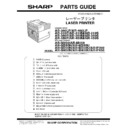
PARTS GUIDE
CONTENTS
The AR-M300N / M300U Parts Guide describes only the parts change from AR-P350 / AR-P450 Parts Guide. for the
common parts, please refer to the AR-P350 / AR-P450(CODE :00ZAR350LPP1/) Parts Guide.
common parts, please refer to the AR-P350 / AR-P450(CODE :00ZAR350LPP1/) Parts Guide.
SHARP CORPORATION
CODE:00ZARM300NP1E
LASER PRINTER
(MULTI FUNCTION)
AR-M300N
MODEL
AR-M300U
1
Exteriors
2
Left door unit
3
PS roller unit
4
Main drive unit
5
TC unit
6
Cassette paper feeder
7
Fusing unit
8
Delivery turn over unit
9
MC unit
F
Process unit
G
Developer unit
H
Controller BOX unit
I
Power supply unit
J
Rear frame section 1
K
Rear frame section 2
L
Cassette unit
M
Packing material & Accessories
N
PCU PWB unit
P
Mother board
Q
Fuse PWB unit
U
AC/DC Power supply PWB 200V
V
MFP control PWB (AR-M300N)
W
STD control PWB (AR-M300U)
■
Index
– 1 –
DEFINITION
The definition of each Rank is as follows and also noted in the list
Rank A : Maintenance parts, and consumable parts which are not included in but closely related to maintenance parts
Rank B : Performance/function parts (sensors, clutches, and other electrical parts), consumable parts
Rank E : Unit parts including PWB
Rank D : Preparation parts (External fitting, packing, parts packed together)
Rank C : Parts other than the above (excluding sub components of PWB)
Rank B : Performance/function parts (sensors, clutches, and other electrical parts), consumable parts
Rank E : Unit parts including PWB
Rank D : Preparation parts (External fitting, packing, parts packed together)
Rank C : Parts other than the above (excluding sub components of PWB)
Because parts marked with "
!
" is indispensable for the machine safety maintenance and operation, it must be replaced with
the parts specific to the product specification.
F
Other than this Parts Guide, please refer to documents Service Manual(including Circuit Diagram)of this model.
F
Please use the 13 digit code described in the right hand corner of front cover of the document, when you place an order.
F
For U.S. only-Use order codes provided in advertising literature. Do not order from parts department.
*
These parts are supplied by SMF
1
Exteriors
2
Left door unit
3
PS roller unit
4
Main drive unit
NO.
PARTS CODE
PRICE
RANK
NEW
MARK
PART
RANK
DESCRIPTION
1
G C A B - 0 9 3 8 F C N Z
AY
D
Right exterior
5
G C A B - 0 9 4 0 F C N 2
BA
D
Paper exit tray exterior
11
H P N L C 0 2 4 3 F C N 1
AP
D
Operation cabinet
13
G C A B - 0 9 3 4 F C N 1
AW
D
Front exterior
14
G C A B - 0 9 3 5 F C N Z
AN
D
Front exterior upper
16
G C A B - 0 9 3 6 F C N 1
AS
D
Upper exterior left
17
G C A B - 0 9 3 7 F C N Z
AL
D
Left exterior rear
20
G C A B - 0 9 3 9 F C N 1
AL
D
Right exterior rear
23
P C O V P 1 5 5 4 F C N Z
AF
C
Harness cover
26
C P N L H 0 0 2 0 Q S 4 3
AN
N
D
Model panel
[ARM300U]
C P N L H 0 0 2 0 Q S 4 4
AN
N
D
Model panel
[ARM300N]
NO.
PARTS CODE
PRICE
RANK
NEW
MARK
PART
RANK
DESCRIPTION
3
L X - B Z 0 1 4 7 F C Z 1
AC
C
Screw
9
P T M E - 0 2 8 7 F C Z 1
AD
C
Transfer lock pawl
13
L A N G T 1 4 0 7 F C Z 2
AR
C
ACC fixing angle F
16
P T M E - 0 2 7 9 F C Z 1
AB
C
Left door lock pawl
19
G D O R - 0 0 3 0 F C N 1
BC
D
Left door
27
N F A N P 0 0 6 9 F C Z Z
AV
B
Fan
32
L A N G T 1 4 0 9 F C Z 1
AH
C
ACC fixing angle R lower
37
L A N G T 1 4 0 8 F C Z 1
AG
C
ACC fixing angle R upper
(Unit)
901
C D O R - 0 0 3 0 D S 5 2
BP
E
Left door unit
NO.
PARTS CODE
PRICE
RANK
NEW
MARK
PART
RANK
DESCRIPTION
24
J K N B Z 0 1 3 9 F C Z 2
AD
C
PS knob
30
N R O L R 1 3 0 4 F C Z 1
AN
C
PS front roller
37
N C P L - 0 0 5 9 F C Z Z
AC
C
PS coupling
38
L X - B Z 0 5 8 9 F C Z 1
AA
C
Screw
NO.
PARTS CODE
PRICE
RANK
NEW
MARK
PART
RANK
DESCRIPTION
15
D H A I - 3 4 2 8 F C Z Z
AR
C
DV interface harness
25
L X - B Z 0 6 7 0 F C Z 1
AC
C
Screw(3
×
8)
34
D H A I - 3 4 2 7 F C Z Z
AN
C
HV harness
57
N G E R H 1 5 2 8 F C Z Z
AE
C
PS Drive Gear
63
N S F T Z 2 5 7 5 F C Z 1
AF
C
PS front roller shaft
67
L X - B Z 0 7 8 8 F C Z 1
AC
C
Screw
71
N S F T Z 2 5 7 6 F C Z 2
AF
C
PS roller shaft
90
M S P R C 3 0 2 7 F C Z 1
AD
C
PS front spring
91
L X - W Z 0 4 2 1 F C Z Z
AA
C
Washer
– 2 –
4
Main drive unit
5
TC unit
6
Cassette paper feeder
7
Fusing unit
8
Delivery turn over unit
8
Delivery turn over unit
NO.
PARTS CODE
PRICE
RANK
NEW
MARK
PART
RANK
DESCRIPTION
3
P G I D M 1 9 5 0 F C Z 2
AE
C
Transfer front PG
12
L H L D Z 1 4 7 4 F C Z 2
AL
C
TR holder
NO.
PARTS CODE
PRICE
RANK
NEW
MARK
PART
RANK
DESCRIPTION
19
L X - B Z 0 9 6 0 F C Z Z
AC
C
Screw(
φ
16)
NO.
PARTS CODE
PRICE
RANK
NEW
MARK
PART
RANK
DESCRIPTION
3
P T M E - 0 2 8 2 F C Z 1
AH
C
Upper separator pawl
11
P C O V P 1 5 4 6 F C Z 1
AY
C
Fusing upper cover
34
M L E V F 0 7 8 8 F C Z 2
AF
C
Pressure lever F
38
M L E V F 0 7 8 9 F C Z 2
AF
C
Pressure lever R
NO.
PARTS CODE
PRICE
RANK
NEW
MARK
PART
RANK
DESCRIPTION
5
N F A N P 0 0 6 9 F C Z Z
AV
B
Fan
10
P G I D M 1 8 9 6 F C Z 1
AV
C
Paper exit upper PG
14
L D A I U 0 6 2 6 F C Z 2
AK
C
Paper exit follower roller fixing plate
15
N R O L R 1 3 1 5 F C Z 2
AM
C
Exit paper roller
20
N R O L R 1 3 1 6 F C Z 2
AT
C
Fusing roller rear
38
N B L T H 0 3 2 7 F C Z 1
AL
C
Belt
47
N B L T H 0 3 5 0 F C Z 1
AH
C
Belt
62
P B R S S 0 2 0 8 F C Z 1
AH
C
Discharge brush
66
P S H E P 4 9 6 2 F C Z 1
AC
C
Belt control sheet
FCP06240
91
FCP06241
66
– 3 –
9
MC unit
F
Process unit
F
Process unit
G
Developer unit
G
Developer unit
NO.
PARTS CODE
PRICE
RANK
NEW
MARK
PART
RANK
DESCRIPTION
3
C P L T M 6 0 4 8 D S 5 1
AL
E
Plate
NO.
PARTS CODE
PRICE
RANK
NEW
MARK
PART
RANK
DESCRIPTION
4
L R A L M 0 1 8 0 F C Z 1
AM
C
TH rail C
8
P M L T - 1 2 4 5 F C Z 2
AE
C
Process U cushion
9
P C O V P 1 5 8 9 F C Z 1
AG
C
Process cover U
16
M S P R C 3 0 1 0 F C Z 1
AB
C
Shutter open close spring
26
L X - B Z 0 6 5 6 F C Z 1
AE
C
Screw
44
P T M E - 0 2 8 6 F C Z 1
AH
C
Separator pawl
45
P R N G F 0 1 0 6 F C Z 2
AC
C
Starling N
47
M S P R C 2 9 5 4 F C Z 2
AB
C
Separator pawl spring
48
P M L T - 1 2 3 8 F C Z 1
AC
C
Toner shild cushion
57
L X - W Z 0 4 4 0 F C Z Z
AC
C
Spacer
58
P S P A Z 1 4 3 1 F C Z Z
AA
C
Spacer A
59
P S P A Z 1 4 3 2 F C Z Z
AA
C
Spacer B
501
D U N T - 0 0 8 3 Y S Z Z
AZ
E
Separation pawl holder unit
NO.
PARTS CODE
PRICE
RANK
NEW
MARK
PART
RANK
DESCRIPTION
19
J H N D P 0 1 6 6 F C B Z
AC
C
SRU handle
29
L P L T M 6 0 2 2 F C Z Z
AC
C
M4 plate
48
P M L T - 1 2 4 1 F C Z 1
AA
C
DV-BOX cushion
49
P M L T - 1 2 4 4 F C Z 1
AC
C
Docter cushion R
56
P M L T - 1 2 9 6 F C Z Z
AH
C
Shutter cushion
57
58
59
FCP06242
56
FCP06243

