Sharp AR-LC1 (serv.man2) Service Manual ▷ View online
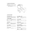
[1] OUTLINE OF THE PRODUCT
This paper feed unit stores about 3300 sheets of A4- or B5-size
paper to save the trouble of adding paper when a large amount of
copies is to be taken.
paper to save the trouble of adding paper when a large amount of
copies is to be taken.
Note: If this large-capacity paper feed unit is to be installed, it is
required to install an optional single-stage paper feed desk
(AR-DE1) or special desk (AR-DD1).
(AR-DE1) or special desk (AR-DD1).
AR-DE2
AR-LC1
[2] SPECIFICATIONS
(1) Paper feed capacity
Paper feed capacity
3300 sheets (64 g/m
2
or equivalent)
(2) Amount detection
Paper amount detection
Provided (5-stage sensors including
empty detection)
empty detection)
Detector
0% (empty),
∼
25%,
∼
50%,
∼
75%,
∼
100%
Paper size detection
None
(3) Paper size
Paper size
A4/B5
Paper weight
56
∼
105 g/m
2
(14
∼
28 lbs) (Same as
the copier’s paper feed section)
(4) Size switching
Switching
to be performed by service personnel
(5) Size detection
Size detection
Setting by simulation
(6) Dehumidifying heater
Yes/No
Yes
ON/OFF switch
ON/OFF by dehumidification heater
switch on the copier
switch on the copier
(7) Factory setting
Factory setting paper
size
size
A4
Plate display
A4
(8) Power supply
Power supply
supplied by the copier
(DC 5 V, DC 24 V)
(DC 5 V, DC 24 V)
(9) Power consumption
Max. power consumption
about 17.6 W
At stand-by
about 1.2 W
(10) External view
External dimensions
325 (wide)
×
536 (deep)
×
572 (high)
mm
Weight
about 32 kg
Case color
Frosty gray
1 – 1
[3] UPACKING AND INSTALLATION
1. Unpacking
1
Upper cushion
2
Installation manual
3
LCC
4
Lower cushion
5
Packing case
2
1
1
3
5
4
4
2. Installation procedure
Parts included
Remove the power cord from the copier and then
perform the following procedure.
perform the following procedure.
1. Mount the upper mounting plates and the mounting
plate.
Make 6 holes for mounting (indicated with
) on the copier and
lower part of the stand using a Phillips screwdriver, etc. and remove
burs using a flat-blade screwdriver, etc.Mount the upper mounting
plates using screws A (two for each plate).
burs using a flat-blade screwdriver, etc.Mount the upper mounting
plates using screws A (two for each plate).
Then remove 2 screws from the LCC cover on the copier and remove
the LCC cover.
the LCC cover.
Securing plate
(1 pc.)
Upper mounting plates
(2 pcs.)
Mounting plate
(1 pc.)
Connecting plate
(1 pc.)
Screws A (6 pcs.)
Screw B (1 pc.)
Screws C (2 pcs.)
Hole for mounting
Hole for mounting
Screws A
Screws A
Screws A
Screw
Screw
Upper
mounting plate
mounting plate
Upper
mounting plate
mounting plate
LCC cover
Mounting plate
3 – 1
2. Mount the connecting plate to the large capacity tray.
Note: Before mounting the connecting plate to the large capacity
tray, be sure to remove the 2 step screws for securing the
bottom plate.
bottom plate.
Fit the connecting plate to the lower part of the large capacity tray
and mount the plate to the position indicated with A using screw B.
and mount the plate to the position indicated with A using screw B.
3. Fit the connecting plate of the large capacity tray to
the mounting plate of the stand.
Insert the connecting plate into the mounting plate of the stand while
lifting the large capacity tray a little.
lifting the large capacity tray a little.
After insertion, move the large capacity tray away from the copier to
check that the tray is locked.While the tray is locked, mount the
securing plate using 2 screws C.
check that the tray is locked.While the tray is locked, mount the
securing plate using 2 screws C.
4. Check and adjust the height of the large capacity tray.
Move the large capacity tray toward the copier and adjust the tray
and check it so that the rib of the large capacity tray is flush with the
axis of the mounting plate which has been mounted to the copier as
shown in the figure.
and check it so that the rib of the large capacity tray is flush with the
axis of the mounting plate which has been mounted to the copier as
shown in the figure.
•
If the axis is flush with the rib:
Push the large capacity tray toward the copier.
•
If the axis is not flush with the rib:
Loosen the 2 screws of the installation adjuster mounting plate lo-
cated at the lower part of the large capacity tray and adjust as fol-
lows:
cated at the lower part of the large capacity tray and adjust as fol-
lows:
★
If the rib is to the right of the axis
Turn the knob clockwise to adjust.
After adjustment, tighten the 2 screws of the installation adjuster
mounting plate.
mounting plate.
★
If the rib is to the left of the axis
Turn the knob counterclockwise to adjust.
After adjustment, tighten the 2 screws of the installation adjuster
mounting plate.
mounting plate.
‚`
‚a
‚`
‚a
Screw B
Step screws
Connecting plate
1
2
Mounting plate
Connecting plate
Securing plate
Screws C
Top view
Axis
Rib
Top view
Axis
Rib
Knob
Screw
Top view
Axis
Rib
Knob
Screw
3 – 2
5. Connect the connector of the large capacity tray.
Remove the connector cover securing screw for connection of the
large capacity tray relay harness connector and remove the connec-
tor cover.Then connect the large capacity tray relay harness connec-
tor to the connector of the copier and tighten the screw on the con-
nector to secure the connector.
large capacity tray relay harness connector and remove the connec-
tor cover.Then connect the large capacity tray relay harness connec-
tor to the connector of the copier and tighten the screw on the con-
nector to secure the connector.
6. Remove the feed table securing screw and securing
materials.
Pull out gently the paper tray of the large capacity tray until it
stops.Remove the feed table securing screw and 5 securing materials
which secure the feed table of the large capacity tray.
stops.Remove the feed table securing screw and 5 securing materials
which secure the feed table of the large capacity tray.
Push back gently the paper tray to its original position.
To use the large capacity tray without changing the paper size from
the factory default setting:
the factory default setting:
★
Proceed to step 12 of this installation manual.
At this time, insert the power plug of the copier to an outlet and turn
the power switch to the "ON" position.
the power switch to the "ON" position.
★
Factory default setting: A4 size
The paper size can be switched only to the B5 size.
To use the large capacity tray after changing the paper size from the
factory default setting:
factory default setting:
7. Remove the stopper from the paper tray.
Pull out gently the paper tray until it stops and remove the stopper
securing screw located on the lower part of the right side to remove
the stopper.
securing screw located on the lower part of the right side to remove
the stopper.
Then pull out again the paper tray until it stops.
8. Switch the rear end shaft.
Remove each rear end shaft securing screw (blue) which secures the
rear end shaft to the right side in the paper tray and remove the 2
rear end shafts.
rear end shaft to the right side in the paper tray and remove the 2
rear end shafts.
Then fit the lower part of each removed rear end shaft to the mount-
ing hole of the feed table of the paper tray and secure the upper part
to the position with B5 indication using a securing screw (blue).
ing hole of the feed table of the paper tray and secure the upper part
to the position with B5 indication using a securing screw (blue).
Securing screw
Connector cover
Screw
Connector
Securing materials
Securing materials
Feed table securing screw
Feed table
Stopper
Securing screw
Rear end shafts
Securing screw (blue)
Securing screw (blue)
Securing screw (blue)
Rear end shafts
Feed table
Mounting holes
3 – 3

