Sharp AR-FN5 (serv.man2) Service Manual ▷ View online
B. Operations of each section when the power it turned on
Unit
No.
Operation
Remark
Alignment unit
Escape transport upper unit
1
Finisher paper entry detection
OP: Paper provided. JAM display
CL: Paper empty. Go to READY
CL: Paper empty. Go to READY
2
Paper width detection
3
Transport switch gate right drive
4
Transport switch gate left drive
Escape transport lower unit
5
Upper alignment plate drive
Alignment tray unit
6
Side guide plate alignment drive
7
Rear edge plate alignment drive
8
Rear edge plate drive
9
Side guide plate home position
10
Rear edge plate unit home position
11
Shutter drive
12
Tray paper empty detection
Staple unit
13
Staple empty detection
14
Cartridge empty detection
15
Stapling operation
16
Home position detection
17
Self priming
Others
18
Staple supply cover open/close detection
19
Tray JAM process detection
Paper exit tray unit
Escape tray
20
No. 1 tray paper exit detection
21
JAM process PG open/close detection
Lift-up tray
22
No. 2 tray paper exit detection
23
Lift-up drive
24
Lift-up drive rotation control
25
Tray position detection (upper)
26
Paper position detection
27
Tray position detection (lower)
28
Tray offset drive
29
Offset home position
Main drive system
30
Main rotation drive
31
Paper exit roller rotation control
5. Operational specifications of each section
(1) Operational specifications of side guide plate
Pulse motor specifications and control
·
1 step = 7.5 degrees
·
1-2 phase drive 1200pps
·
Reduction ratio 15P
®
40P = 24P (MXL tooth shape)
·
Side guide plate shift for an input of 1 pulse: 0.1905mm / pulse
·
Slow up/down control for tuning:
Basic operations of side guide plate
1. Moving to the standby position
·
The side guide plate is moved from the home position to the
standby position according to the paper size information supplied
by the main body.
standby position according to the paper size information supplied
by the main body.
Paper width (mm) Shift quantity (mm) Pulse number (pluse)
A3, A4
297
0
0
B4, B5
257
22.1
116
A4R
210
45.5
239
WLT, LT
279.4
12.4
65
RG, LTR,GLG
215.9
42.7
224
·
The pulse number is rounded at the first digit below the decimal
point.
point.
2. Alignment operation start
·
Alignment operation is started at timer control after the paper
entry sensor is turned OFF.
entry sensor is turned OFF.
¯
Timer time = 59.6(mm) / 122(mm/s) +
a
= About 0.7
3. Shift quantity in alignment
Paper width (mm) Shift quantity (mm) Pulse number (pluse)
A3, A4
297
27.4
144
B4, B5
257
45.3
238
A4R
210
69.0
362
WLT, LT
279.4
32.0
168
RG, LTR,GLG
215.9
65.9
346
·
The pulse number is rounded at the first digit below the decimal
point.
point.
4. Alignment operation
·
Reciprocating operations in the above shift quantity are per-
formed. At the last page, the plate stops at a position about 2mm
from the edge.
formed. At the last page, the plate stops at a position about 2mm
from the edge.
®
Staple process
¯
The last return is made by the pushing quantity (2).
·
For provisonal alignment paper (B4 or less), the rear edge plate
passes under a bundle of paper to reach the home position, and
stands by at a position slightly wider than the paper width (about
2mm) until the final alignment is performed toward the shutter.
After completion of the final alignment, the plate stops at a posi-
tion about 2mm from the edge similarly to the above, and stapling
is performed.
5. Paper exit operation
·
When a bundle of paper is discharged after stapling, the side
guide plate moves to a position so as not to interfere discharging
and to prevent against skew feeding of the bundle.
guide plate moves to a position so as not to interfere discharging
and to prevent against skew feeding of the bundle.
¯
Paper width 12pulse (about 2.3mm)
6. Next job
·
The rear edge plate pushes paper by specified distance, and
returns to the home position. The above procedures are repeated
for the next job.
returns to the home position. The above procedures are repeated
for the next job.
·
If the operation is completed with one job, the plate returns to the
home position.
home position.
(2) Operational descriptions of rear edge plate
Pulse motor specifications and control
·
1 step = 7.5 degrees
·
1-2 phase drive 847pps (600pps when discharging a paper bun-
dle)
dle)
·
Reduction ratio 15P
®
20P = 26P
·
Side guide plate shift for an input of 1 pulse: 0.141275mm / pulse
·
Slow up/down control for tuning
Basic operations of side guide plate
1. Moving to the standby position
The side guide plate is moved from the home position to the
standby position according to the paper size information supplied
by the main body.
standby position according to the paper size information supplied
by the main body.
The standby position and the alignment operations differ depend-
ing on the following two size groups:
ing on the following two size groups:
A3, WLT
B4, LG, FC, A4, B5, A4R, LT, LTR
B4, LG, FC, A4, B5, A4R, LT, LTR
Paper width (mm)
Shift quantity (mm)
Pulse number (pluse)
WLT
431.8
24.8
60
A3
420
24.8
60
B4
384
395.0
957
RG
355.6
393.8
954
GLG
330.2
368.6
893
A4R
297
335.2
812
LTR
279.4
317.8
770
LT
215.9
254.3
616
A4
210
248.5
602
B5
182
220.4
534
2. Alignment operation start
Alignment operation is started at timer control after the paper
entry sensor is turned OFF.
entry sensor is turned OFF.
¯
Timer time = 59.6(mm) / 122(mm/s) +
a
= About 0.7
3. Shift quantity in alignment
Paper width (mm)
Shift quantity (mm)
Pulse number (pluse)
WLT
431.8
9.9
24
A3
420
20.6
50
B4
384
1.7
4
RG
355.6
7.4
18
GLG
330.2
8.3
20
A4R
297
8.3
20
LTR
279.4
8.3
20
LT
215.9
8.3
20
A4
210
8.3
20
B5
182
8.3
20
·
The pulse number is rounded at the first digit below the decimal
point.
point.
4. Alignment operation
·
A3, WLT
Reciprocating alignment operation in the above shift quantity is
performed toward the shutter. At the last page, the plate stops at a
position about 2mm from the edge.
performed toward the shutter. At the last page, the plate stops at a
position about 2mm from the edge.
®
Stapling process
·
B4 or less
Reciprocating alignment operation in the above shift quantity is
performed toward the provisional alignment reference wall. After
the last page is aligned, the rear edge is put down, and the unit
returns to the home position. After detection of the home position,
the rear edge plate is raised and the bundle of paper is transported
to the shutter. After completion of the final page alignment, the
plate stops at the paper edge.
®
Stapling process
5. Paper exit operation
The stapled bundle of paper is lifted up by the rear edge plate and
pushed to the paper exit roller.
pushed to the paper exit roller.
6. Next job
·
The pushing distance of a paper bundle is a little bit greater than
the distance (71.6mm) between the shutter and the paper exit
roller. After pushing, moves toward the home position without
putting down the rear edge plate. The next job paper which is in
stand-by in front of PS is fed, and the above procedures are
repeated.
If the operation is completed with one job, the paper bundle is
discharged and the plate returns to the home position.
(3) Paper size detection
1. Body Paper-In sensor
Detects the paper size by the ON time.
¯
The following sizes cannot be judged only with the length.
A4 and A5R
A5 and postcard
LT and INVR
Some kinds of envelopes
A4 and A5R
A5 and postcard
LT and INVR
Some kinds of envelopes
2. Width detection of paper before discharging from the body
·
No. 1 tray (escape tray) output inhibition size
¯
Postcards, envelopes
·
No. 2 tray (list-up tray) output inhibition size
¯
A5, A5R, INV. INVR, postcards, envelopes
·
Staple inhibition size
¯
B5R, above uncertain sizes
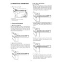
[5] DISASSEMBLY AND ASSEMBLY
For disassembly, follow the sequence of the illustration numbers. For
assembly, reverse the disassembly procedures.
assembly, reverse the disassembly procedures.
For disassembly and assembly of parts which are not described in this
manual, refer to the Parts Guide.
manual, refer to the Parts Guide.
1. Finisher
A. Alignment plate unit
1-A-1
1-A-2
1-A-3
1-A-4
4)
1)
2)
3)
1)
2)
4)
3)
1)
2)
3)
1-A-5
B. Paper exit unit
1) Remove the alignment unit.
1-B-1
1-B-2
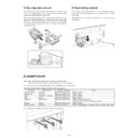
2. Stapler unit
1) Remove the alignment unit.
2-1
3. Paper exit unit and each roller
Move down the offset tray unit to the bottom, and remove the paper
exit unit from the copier.
Then remove the rollers from the paper exit unit.
exit unit from the copier.
Then remove the rollers from the paper exit unit.
Procedures to move down the offset tray unit to the bottom
When turning on the power, lift the paper holding lever which
detects the top of the tray with your fingers.
When the tray reaches the bottom, turn off the power. (When
the lever moves about half of the moving distance, you may
release your fingers, and the tray will fall to the bottom.)
detects the top of the tray with your fingers.
When the tray reaches the bottom, turn off the power. (When
the lever moves about half of the moving distance, you may
release your fingers, and the tray will fall to the bottom.)
3-1
3-2
1)
1)
2)
1)
2)
3)
1)
2)

